
Related Manuals for SHOWTEC TR-512


Summary of Contents for SHOWTEC TR-512
- Page 1 USER MANUAL ENGLISH TR-512 Install Product code: 50826 Highlite International B.V. – Vestastraat 2 – 6468 EX – Kerkrade – the Netherlands...
- Page 2 TR-512 Install Preface Thank you for purchasing this Showtec product. The purpose of this user manual is to provide instructions for the correct and safe use of this product. Keep the user manual for future reference as it is an integral part of the product. The user manual shall be stored at an easily accessible location.
-
Page 3: Table Of Contents
DMX Cables ..............................13 Setup Examples ..............................14 Program Recording Setup ........................14 Program Playing Setup ..........................15 Connecting External Trigger Devices .....................16 Connecting the TR-512 Install-Wall Panel ..................17 Operation ..............................19 Safety Instructions for Operation ........................19 Start-up ................................19 Control Panel ..............................20 Recording a Program ............................20 Playing a Program ............................20... - Page 4 TR-512 Install Device Label ............................28 DMX Port Option ..........................29 Display Option.............................29 Version ..............................29 Save Configuration ............................30 Load Configuration ............................31 Default Setting .............................31 Troubleshooting ............................32 Maintenance .............................. 33 Preventive Maintenance ..........................33 Basic Cleaning Instructions ........................33 Corrective Maintenance ..........................33 Deinstallation, Transportation and Storage ....................34 10.
-
Page 5: Introduction
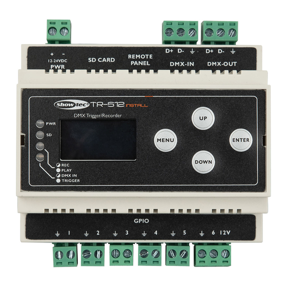
The manufacturer will not accept liability for any resulting damages caused by the non-observance of this manual. After unpacking, check the contents of the box. If any parts are missing or damaged, contact your Highlite International dealer. Your shipment includes: ● Showtec TR-512 Install ● MicroSD card ● User manual Fig. 01 Intended Use This device is designed to be used as a professional DMX trigger/recorder. -
Page 6: Symbols And Signal Words
TR-512 Install Symbols and Signal Words Safety notes and warnings are indicated throughout the user manual by safety signs. Always follow the instructions provided in this user manual. Indicates an imminently hazardous situation which, if not avoided, will result in DANGER death or serious injury. -
Page 7: Safety
TR-512 Install Safety Important Read and follow the instructions in this user manual before installing, operating or servicing this product. The manufacturer will not accept liability for any resulting damages caused by the non-observance of this manual. Warnings and Safety Instructions... -
Page 8: Requirements For The User
TR-512 Install Attention Do not expose the device to conditions that exceed the rated IP class conditions. This device is IP20 rated. IP (Ingress Protection) 20 class provides protection against solid objects greater than 12 mm, such as fingers, and no protection against harmful ingress of water. -
Page 9: Description Of The Device
Description of the Device The TR-512 Install is a compact but very powerful tool which can be used for triggering any light show or scene in a simple way. It can record and play several DMX programs at the same time. Those programs can be stored on a microSD card. -
Page 10: Product Specifications
TR-512 Install Product Specifications Model: TR-512 Install Electrical: Power supply (external): 12 V DC Power consumption: Physical: Dimensions: 105 x 110 x 58 mm (LxWxH) Weight: 0,19 kg Operation and control: Control protocols: DMX-512 Control panel: OLED display and buttons... -
Page 11: Dimensions
TR-512 Install Dimensions Fig. 03 Product code: 50826... -
Page 12: Installation
TR-512 Install Installation Safety Instructions for Installation WARNING Incorrect installation can cause serious injuries and damage of property. The installation of this device shall be carried out only by instructed or skilled persons. Before installing the device, make sure that the electrical enclosure, where the device will be mounted, is disconnected from power supply. -
Page 13: Connecting To Power Supply
03) Put the Phoenix connector back in the TR-512 Install. 04) Install the TR-512 Install on a DIN rail. See 4.3. DIN Rail Mounting on page 11 for more information. 05) Connect the external power supply to the socket-outlet with its power plug. -
Page 14: Setup
DMX Connection DMX-512 Protocol Use a DMX-512 controller to create DMX programs and send them to the TR-512 Install where they will be stored on the microSD card. The TR-512 Install has 3-pin DMX signal IN and OUT Phoenix terminal connectors. -
Page 15: Setup Examples
TR-512 Install Setup Examples Program Recording Setup 01) Remove the 3-pin Phoenix terminal DMX connector IN (05) and the 3-pin Phoenix terminal DMX connector OUT (06). Fig. 08 02) Connect a DMX-512 light controller to the device’s 3-pin Phoenix terminal DMX connector IN (05) and connect light fixtures to the device’s 3-pin Phoenix terminal DMX connector OUT (06). -
Page 16: Program Playing Setup
03) Connect the external trigger devices. See 5.3.2.1. Connecting External Trigger Devices on page 16 or 5.3.2.2. Connecting the TR-512 Install-Wall Panel on page 17, for more information. 04) Follow the instructions from 6.5. Playing a Program on page 20. -
Page 17: Connecting External Trigger Devices
TR-512 Install Connecting External Trigger Devices 01) Remove the 2-pin 1–6 GPIO Phoenix terminal connectors IN (09). Fig. 12 02) Connect the desired external trigger devices (movement sensors, temperature sensors, light sensors, etc.) to the device’s 2-pin 1–6 GPIO Phoenix terminal connectors IN (09). -
Page 18: Connecting The Tr-512 Install-Wall Panel
25 m. 02) Install the wall panel in two ways, with or without the jumper. See Fig. 16. ● With the jumper: Set the TR-512 Install to TOGGLE_TR. See 6.9.4.4. Mode on page 27 for more information. ● Without the jumper: Set the TR-512 Install to NO_TR. See 6.9.4.4. Mode on page 27 for more information. - Page 19 TR-512 Install 03) Make sure that the RJ-45 cable has the following pinout: Fig. 17 Product code: 50826...
-
Page 20: Operation
TR-512 Install Operation Safety Instructions for Operation Attention This device must be used only for the purposes it is designed for. This device is designed to be used as a professional DMX trigger/recorder. It is suitable for indoor installation in an electrical enclosure. It is not suitable for households. -
Page 21: Control Panel
02) Assign the recorded program to one of the 6 triggers. See 6.9.4. Trigger Event on page 26 for more information. 03) Activate the external triggers or press the buttons on the TR-512 Install-Wall Panel. The LED indicator (10) will blink once every time a trigger is activated. During playing programs, the LED indicator (11) will be on. -
Page 22: Trigger Monitoring
TR-512 Install Trigger Monitoring You can monitor the current status of each of the 6 triggers. You can access the trigger status menu only from the start screen. 01) Press and hold down the MENU button for 2 seconds in order to return to the start screen, from any place in the menu. -
Page 23: Menu Overview
TR-512 Install Menu Overview Product code: 50826... -
Page 24: Main Menu Options
TR-512 Install Main Menu Options 1. Play Show 2. Record Show 3. Delete Show 4. Trigger Event 5. Stop TR Event 6. Device Settings 7. Save Configuration 8. Load Configuration 9. Default Setting 01) Press the UP/DOWN buttons to toggle through the 9 menus. -
Page 25: Mode
TR-512 Install Mode In this submenu you can play the desired program. 01) Press the UP/DOWN buttons to select ONE PLAY (the program will be played once) or LOOP PLAY (the program will be played in a loop). 02) Press the ENTER button to confirm your choice. -
Page 26: Mode
TR-512 Install Mode In this submenu you can set recording options. 01) Press the ENTER button to open the menu. 02) Press the UP/DOWN buttons to select one of the 3 recording modes: ● MANUAL: Start and stop recording manually. -
Page 27: Trigger Event
TR-512 Install Trigger Event In this menu you can set the trigger event settings. 01) Press the UP/DOWN buttons to select the desired trigger. 02) Press the ENTER button to open the desired trigger’s menu. The display will show: 03) Press the UP/DOWN buttons to toggle through the 5 available submenus: ●... -
Page 28: Show
TR-512 Install 03) Press (or press and hold down, for quick search) the UP/DOWN buttons to select the desired character. 04) Press the ENTER button to confirm your choice. 05) Repeat steps 1–4 to edit the remaining characters. 06) Press the UP/DOWN buttons to select CANCEL (to cancel changes) or ENTER (to save the new name). -
Page 29: Stop Tr Event
TR-512 Install Stop TR Event In this menu you can deactivate the trigger events. 01) Press the UP/DOWN buttons to select one of the 6 trigger events. 02) Press the ENTER button to deactivate the selected trigger event. 03) Repeat steps 1–2 to deactivate the remaining trigger events, if needed. -
Page 30: Dmx Port Option
TR-512 Install DMX Port Option In this submenu you can adjust the port settings. 01) Press the ENTER button to open the menu. 02) Press the UP/DOWN buttons to select one of the 2 modes: ● SINGLE: Only the last triggered program will be played. -
Page 31: Save Configuration
TR-512 Install Save Configuration In this menu you can create a backup of the device’s settings. It will be saved on the microSD card. 01) Press the UP/DOWN buttons to select NAME and press the ENTER button to edit the backup’s name. -
Page 32: Load Configuration
02) Press the ENTER button to confirm your choice. The display will return to the main menu. Note: Turn the TR-512 Install off before removing the microSD card. Use the included microSD card to back up your data and transfer your files to a regular PC. -
Page 33: Troubleshooting
TR-512 Install Troubleshooting This troubleshooting guide contains solutions to problems which can be carried out by an ordinary person. The device does not contain user-serviceable parts. Unauthorized modifications to the device will render the warranty void. Such modifications may result in injuries and material damage. -
Page 34: Maintenance
TR-512 Install Maintenance Maintenance and cleaning shall be carried out only by instructed persons. Follow the maintenance schedule established for the site where the electrical enclosure is installed. Disconnect power supply before servicing or cleaning. Preventive Maintenance Attention Before use, examine the device visually for any defects. -
Page 35: Deinstallation, Transportation And Storage
TR-512 Install Deinstallation, Transportation and Storage ● Disconnect the electrical enclosure, where the device is mounted, from the power supply before deinstallation of the device. ● Use the original packaging to transport the device, if possible. ● Clean the device before storing. Follow the cleaning instructions in chapter 8.1.1. Basic Cleaning Instructions on page 33. - Page 36 ©2021 Showtec...
Need help?
Do you have a question about the TR-512 and is the answer not in the manual?
Questions and answers