Advertisement
Quick Links
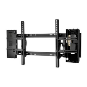
Installation and Assembly:
Wireless Tilt Wall Mount for 37" - 63"
Flat Panel Displays
Models: WL-ST660-200
Max Load Capacity:
200 lb (90 kg)
2300 White Oak Circle • Aurora, Il 60502 • (800) 865-2112 • Fax: (800) 359-6500 • www.peerless-av.com
ISSUED: 08-24-12 SHEET #: 180-9038-2 10-30-12
Advertisement

Subscribe to Our Youtube Channel
Related Manuals for peerless-AV WL-ST660-200


Summary of Contents for peerless-AV WL-ST660-200
- Page 1 Wireless Tilt Wall Mount for 37" - 63" Flat Panel Displays Models: WL-ST660-200 Max Load Capacity: 200 lb (90 kg) 2300 White Oak Circle • Aurora, Il 60502 • (800) 865-2112 • Fax: (800) 359-6500 • www.peerless-av.com ISSUED: 08-24-12 SHEET #: 180-9038-2 10-30-12...
- Page 2 NOTE: Read entire instruction sheet before you start installation and assembly. WARNING • Do not begin to install your Peerless product until you have read and understood the instructions and warnings contained in this Installation Sheet. If you have any questions regarding any of the instructions or warnings, for US customers please call Peerless customer care at 1-800-865-2112, for all international customers, please contact your local distributor.
- Page 3 Before you begin, make sure all parts shown are included with your product. Parts List WL-ST660-200 Description Qty. Part # A wall plate 201-1944 B right tilt bracket 201-1472 C left tilt bracket 201-1470 D #14 x 2.5" wood screw...
- Page 4 Verify that the Transmitter is set to the appropriate input port. © 2012 Peerless Industries, Inc. Peerless-AV™ is a trademark of Peerless Industries, Inc. All rights reserved. HD Flow™ is a trademark of I Do It, LTD. Other parties’ marks are the property of their respective owners. hdflow.com...
- Page 5 Installation to Double Wood Stud Wall WARNING • Installer must verify that the supporting surface will safely support the combined load of the equipment and all attached hardware and components. • Tighten wood screws so that wall plate is fi rmly attached, but do not overtighten. Overtightening can damage the screws, greatly reducing their holding power.
- Page 6 Installation to Solid Concrete or Cinder Block WARNING • When installing Peerless wall mounts on cinder block, verify that you have a minimum of 1-3/8" (35mm) of actual concrete thickness in the hole to be used for the concrete anchors. Do not drill into mortar joints! Be sure to mount in a solid part of the block, generally 1"...
- Page 7 Wireless Receiver and Power Enclosure Installation NOTE: The Wireless Receiver Assembly (G) and Power Module Assembly (H) position can be interchanged based on the display’s connector panel location. Install Wireless Receiver Assembly on the side closest to the connector panel. Loosely attach the enclosure mounting brackets (I) to the wireless receiver assembly (G) with two 1/4-20 decorative screws (J) and two 1/4-20 nuts (K) as shown in fi...
- Page 8 Installing Tilt Brackets WARNING • Tighten screws so tilt brackets are fi rmly attached. Do not tighten with excessive force. Overtightening can cause stress damage to screws, greatly reducing their holding power and possibly causing screw heads to become detached. Tighten to 40 in. • lb (4.5 N.M.) maximum torque. •...
- Page 9 Begin with longer length screw, hand thread through multi-washer, tilt bracket and spacer in that order into display as shown below. Screw must make at least three full turns into the mounting hole and fi t snug into place. Do not over tighten. If screw cannot make three full turns into the display, select a shorter length screw from the baffl...
- Page 10 Untie the wireless receiver power adapter cord and route as shown below. Plug the end of the power adapter into the outlet marked DC on the wireless receiver as shown in detail 3. Coil up the excess cord and secure with a cable tie (N).
- Page 11 Close the top cover of the wireless receiver assembly (G), making sure that the IR receiver cord runs underneath the cable opening as shown below. Re-install the two #8 screws. #8 SCREWS CABLE OPENING Install the cable tie anchor (L) onto the inside Plug the power cord from your display into the triple back wall of the power enclosure (H).
- Page 12 Plug extension cord (not included) into power adapter. Plug the component cable(s) from your display (HDMI shown) into the wireless receiver. COMPONENT CABLE EXTENSION CORD B & C Mounting and Removing Flat Panel Display WARNING • Always use an assistant or mechanical lifting equipment to safely lift and position the fl...
- Page 13 13 of 14 ISSUED: 08-24-12 SHEET #: 180-9038-2 10-30-12 © 2012 Peerless Industries, Inc. Peerless-AV® is a registered trademark of Peerless Industries, Inc. All rights reserved. All other brand and product names are trademarks or registered trademarks of their respective owners.
- Page 14 Peerless Industries, Inc. (“Peerless-AV®”) warrants to original end-users of Peerless-AV® products that Peerless-AV® products will be free from defects in material and workmanship, under normal use, for the periods listed below, from the date of purchase by the original end-user. At its option, Peerless-AV® will repair or replace with new or refurbished products or parts, or refund the purchase price of any Peerless-AV®...
Need help?
Do you have a question about the WL-ST660-200 and is the answer not in the manual?
Questions and answers