Table of Contents
Advertisement
Quick Links
Advertisement
Table of Contents

Related Manuals for Mi-T-M AM1-PE02-08M


Summary of Contents for Mi-T-M AM1-PE02-08M
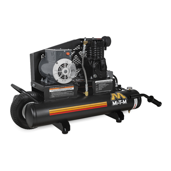
- Page 1 PARTS LIST FOR AIR COMPRESSORS AM1-PE02-08M AM1-PE02-20M PHASE: SINGLE VOLTS: 115/ 208 - 260 MAXIMUM AMPS: 18.8/ 10.2 - 9.4 MAXIMUM PRESSURE: 125 PSI COMPRESSOR OIL GRADE: SAE 30W Non-Detergent COMPRESSOR OIL CAPACITY: 10.0 oz. ©Copyright 2009, Mi-T-M Corporation® EX-9746-061616...
-
Page 2: Table Of Contents
Each component has been rigorously tested to insure the highest level of acceptance. The contents of this Parts Listing are based on the latest product information available at the time of publication. Mi-T-M reserves the right to make changes in price, color, materials, equipment, specifications or models at any time without notice. -
Page 3: Specifications
268 lbs. DIMENSIONS: Basic L x W x H 44.5” x 18.5” x 25” 40” x 24” x 32” Shipping L x W x H 45” x 19” x 32” 47” x 32” x 47” ©Copyright 2009, Mi-T-M Corporation® EX-9746-061616... -
Page 4: Flow Chart
FLOW CHART ©Copyright 2009, Mi-T-M Corporation® EX-9746-061616... -
Page 5: General Theory Of Operation
SAFETY RELIEF VALVE (21). When the TANK PRESSURE GAUGE (22) registers less than 10 PSI, drain the condensation from the AIR TANK (16) by opening the TANK DRAIN (26). ©Copyright 2009, Mi-T-M Corporation® EX-9746-061616... -
Page 6: Tank Assembly For Am1-Pe02-08M
TANK ASSEMBLY FOR AM1-PE02-08M ©Copyright 2009, Mi-T-M Corporation® EX-9746-061616... - Page 7 AM1-PE02-08M 033016 ALC AM1-PE02-08M ITEM DESCRIPTION PART # ITEM DESCRIPTION PART # HANDLE GRIP 7-0059 SPACER 33-0358 PETCOCK 23-0312 AIR COMPRESSOR PUMP 3-0315 DECAL - TANK DRAIN (SEE 71-2001) AIR FILTER ASSEMBLY 19-0253 ISOLATOR 14-0069 FILTER 19-0252 BOLT 27-0015 STRAIN RELIEF...
-
Page 8: Tank Assembly For Am1-Pe02-20M
TANK ASSEMBLY FOR AM1-PE02-20M ©Copyright 2009, Mi-T-M Corporation® EX-9746-061616... - Page 9 SPACER 33-0358 PRESSURE GAUGE 22-0271 BRACKET 20-1134A01 NIPPLE 24-0010 WASHER 28-0003 PLUG 24-0082 BOLT 27-8040 MANIFOLD 24-0266 DECAL - CHECK OIL SAFETY VALVE 22-0228 SHEAVE 10-0150 DECAL SET 71-2001 *MUST ORDER IN ONE FOOT LENGTHS ©Copyright 2009, Mi-T-M Corporation® EX-9746-061616...
-
Page 10: Single Stage Compressor (3-0315)
SINGLE STAGE COMPRESSOR (3-0315) ©Copyright 2009, Mi-T-M Corporation® EX-9746-061616... - Page 11 46-1359 C-CLIP 46-1351 46-1352 OIL SEAL 26-0326 BOLT 27-8033 PISTON RING KIT 70-0534 PISTON OIL RING PISTON RING SIGHT GLASS 46-1336 PLUG 24-0009 KIT - PUMP GASKETS (Includes #’s 8, 12, 15, & 20) 70-0536 ©Copyright 2009, Mi-T-M Corporation® EX-9746-061616...
-
Page 12: Wiring Schematic
WIRING SCHEMATIC ©Copyright 2009, Mi-T-M Corporation® EX-9746-061616... -
Page 13: Wiring Diagram (115 Volt)
WIRING DIAGRAM (115 VOLT) ©Copyright 2009, Mi-T-M Corporation® EX-9746-061616... -
Page 14: Wiring Diagram (230 Volt)
WIRING DIAGRAM (230 VOLT) ACWD-0002 D-040402-RD WIRING DIAGRAM (230 VOLT) PART # DESCRIPTION QTY. 32-0003 Fork Terminal #14 Wire 32-0099 Ring Terminal #14 Wire ©Copyright 2009, Mi-T-M Corporation® EX-9746-061616... -
Page 15: Notes
NOTES ©Copyright 2009, Mi-T-M Corporation® EX-9746-061616... - Page 16 Manufactured by Mi-T-M 50 MI-T-M Drive, Peosta IA 52068 563-556-7484/ Fax 563-556-1235 ©Copyright 2009, Mi-T-M Corporation® EX-9746-061616...
Need help?
Do you have a question about the AM1-PE02-08M and is the answer not in the manual?
Questions and answers