Grundfos Fire NKF Series Installation And Operating Instructions Manual
Diesel driven firefighting system
Hide thumbs
Also See for Fire NKF Series:
- Installation and operating instructions manual (197 pages)

Related Manuals for Grundfos Fire NKF Series


Summary of Contents for Grundfos Fire NKF Series
- Page 1 GRUNDFOS INSTRUCTIONS Fire NKF EN 12845 Diesel driven firefighting system Installation and operating instructions...
-
Page 3: Table Of Contents
English (GB) Installation and operating instructions Original installation and operating instructions. Service, accessories, spare parts Technical data CONTENTS 15.1 Fire pump set 15.2 Sound pressure level Page 15.3 Pump General warning 15.4 Battery Symbols used in this document Operating conditions General information 16.1 Maximum operating pressure... -
Page 4: Symbols Used In This Document
Only use the pumps and pump sets for the • stickers with safety instructions. applications mentioned. Any other use is considered improper. Grundfos cannot be held 3. General information responsible for damage caused by improper use. The risk is carried solely by the operator. - Page 5 3.4.1 Lifting the pump set 3.4.3 Pump Apply a suitable antirust agent on all machined, non-coated Warning surfaces. If the pump is to be stored for more than six months When lifting the entire pump set, use the lifting before startup, treat the inner pump components with a suitable eyes specifically marked on the base frame.
-
Page 6: Product Description
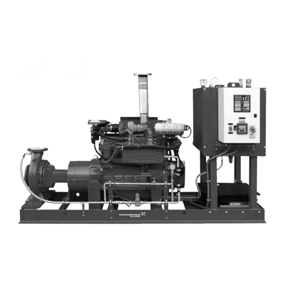
4.2 Applications Grundfos NKF pumps and Fire NKF pump sets are designed for firefighting applications for supplying water to hose reels, fire hydrants or sprinkler systems. Do not use the pump sets for ordinary pumping of liquids or pressure boosting. - Page 7 21 24 Fig. 3 Example of a diesel-powered Fire NKF pump set, left view Pos. Component Pos. Component Base frame Cooling circuit Pump Generator with V-belt and cover Coupling with coupling guard Starter Engine, complete Starter relay Controller Starter batteries Fuel tank Diesel injection pump Tank cap...
-
Page 8: Pump
4.4 Pump 5. Identification The pump is a non-self-priming, single-stage Grundfos NKF 5.1 Pump standard pump with volute casing. It has an axial suction port and a radial discharge port with EN 1092-2-compliant flanges. 5.1.1 Nameplate (pump) For technical data see page 27 chapter 15.3.1 Permissible flange The nameplate shows all important data of the pump. -
Page 9: Pump Set
Made in Germany - P1 Week(yy.ww): Pump version AH: NKF bare shaft pump A2: NKF pump set Grundfos Pumpenfabrik GmbH Willy - Pelz - StraBe 1.5 23812 Wahlstedt GERMANY Pipe connection Fig. 5 Nameplate of an EN pump set DIN flange Materials Pos. -
Page 10: Type Key (Pump Set)
5.3 Type key (pump set) Example Fire -250 /270 Grundfos firefighting systems Pump type Pump for firefighting Nominal diameter of discharge port [mm] Pump housing size [mm] Actual impeller diameter [mm] Driver type D: Diesel engine E: Electric motor, 50 Hz... -
Page 11: Mechanical Installation
You must not disconnect any parts of the entire 1. To control the maximum temperature to 25 °C at the engine air pump set without guidance by Grundfos Service. filter inlet with the engine running at rated load. 2. To supply air for engine combustion. -
Page 12: Foundation
6.2 Foundation As ordinary concrete does not set shrink-freely, the resulting gap must be grouted with a suitable, shrink-free hardening and high- strength or reinforced undercast (i.e. Pagel V1 or Eurogrout The instructions in this section are Premium) to have a force-fit connection between the base frame recommendations. -
Page 13: Mounting The Pump Set
6.3 Mounting the pump set 6.4 Alignment Warning Careful alignment is important for a long service Lift the pump set by means of the lifting eyes of life of the coupling. This is particularly important Caution the base frame. Never use the lifting eyes of the at increased engine speed. -
Page 14: Pipe Connection
Checking the alignment 6.5 Pipe connection Warning The pipework must not stress the pump housing Disconnect the battery cable before you remove or transfer any forces to the pump housing. Caution the coupling guard. See permissible flange forces and torques in Beware of the sharp edges of the coupling guard. -
Page 15: Bypass Pipe
6.7 Bypass pipe Install a pipe on the discharge side of the heat exchanger. See fig. 18. The nominal diameter of the pipe must not be smaller 6.7.1 Air-cooled engine than the outlet of the heat exchanger (1 1/4" or 1 1/2"). Install a bypass pipe from the suction side of the pump to the test pipe to guarantee that the pump is not running against a closed valve. -
Page 16: Exhaust System
6.9 Exhaust system This section applies to pump sets with diesel Note engine. Warning Exhaust must be directed safely to the open air through the exhaust system. Exhaust must not escape indoors. Operation without an exhaust system is not safe. Warning Make sure that persons cannot accidentally come into contact with hot exhaust pipes. -
Page 17: Separate Fuel Tank
6.10 Separate fuel tank Observe the standards when sizing and installing Note a separate fuel tank. You can also install the fuel tank separately in some designs. In these cases, install the fuel tank in a dry and well-ventilated room and as close as possible to the pump set. 6.10.1 Fuel tank installation The fuel tank outlet must be placed higher than the centerline of the high-pressure fuel pump at the engine. -
Page 18: Separate Control Cabinet
6.11 Separate control cabinet 6.11.1 Flex version For the "Flex" version, the control cabinet is mounted onto the separate fuel tank. In this case, place the controller as close to the pump as possible and within view of the pump set. The control cabinet must also be easily accessible. -
Page 19: Electrical Installation
7. Electrical installation 7.3 Connection to battery Before connecting the battery set(s), switch off Warning Caution the power supply by setting the main switch to The electrical installation must be carried out by "O". an authorised staff in accordance with local 12 V version regulations and the wiring diagram in the control cabinet. -
Page 20: Commissioning
8. Commissioning The diagram in figure 27 is used as reference. 8.1 Overview of a firefighting application Fig. 27 Overview of a firefighting application Pos. Description Pos. Description Pos. Description Fire pump, electric powered Overflow Overpressure backflow string Fire pump, diesel powered Pressure tank Fire hydrant Jockey pump... -
Page 21: Preparations Before Commissioning
8.2 Preparations before commissioning Warning The actions below are valid for applications with flooded suction Exhaust must be directed safely to the open air conditions. through the exhaust system. 1. Check that all screws are tight. Exhaust must not escape indoors. 2. -
Page 22: Checking The Function
8.4 Checking the function 10.3 Manual operation You can also start and stop the pump set manually for a This section applies to pump sets with diesel Note functional test, for restarting or after service work. engine. In connection with commissioning, perform a final test run Do not leave the pump room during manual according to the standard applying to the pump set: operation. -
Page 23: Maintenance
12. Maintenance 12.2 Maintenance interval The list below is not complete. See also the Note Warning standard applying to the pump set. Maintenance must be carried out by authorised If not otherwise stated in the standard applying to the pump set or staff. -
Page 24: Pump Set
12.3 Pump set Warning • Check that all screws are tight and not corroded. Fuel vapours are flammable. Therefore, never top • Check all safety devices such as coupling guard. up fuel when the engine is running or when the •... -
Page 25: Fault Finding
13. Fault finding 13.1 Pump set with diesel engine Warning Before starting service work, make sure that the pump set cannot accidentally start. Fault Cause Remedy 1. Pump delivers no or a) Air in suction pipe. Fill priming tank with water and vent pump. Make sure too little water. -
Page 26: Service, Accessories, Spare Parts
Grundfos are not inspected or approved by provide the appropriate spare parts. Grundfos either. To place an order for service parts, please contact Grundfos. The installation and/or use of such products may negatively alter Please inform us about the serial number of the pump set and and thus impair the specified properties of the pump set. -
Page 27: Technical Data
80 ± 16 4, 8 120 ± 24 If not all loads reach the maximum permissible value, one of the values may exceed the normal limit. Contact Grundfos for further 120 ± 24 information. 15.3.1 Permissible flange forces and flange torques 15.4 Battery... -
Page 28: Operating Conditions
16. Operating conditions 16.3 Maximum inlet pressure The actual inlet pressure + closed-valve pressure must always be Do not charge the batteries by an external lower than the maximum operating pressure. See section Caution charger when they are connected to the 16.1 Maximum operating pressure. -
Page 29: Effect Of Ambient Temperature And Altitude On Engine Output
This product or parts of it must be disposed of in an environmentally sound way: 1. Use the public or private waste collection service. 2. If this is not possible, contact the nearest Grundfos company or service workshop. Subject to alterations. - Page 30 [DNd] [kg] outlet [kg] L x W x H [mm] [kg] NKF 32-200 LC2A-NL30 DN 50 DN 32 ANSI 2" Contact Grundfos LC2A-NL30 Contact Grundfos NKF 40-250 DN 65 DN 40 ANSI 2" LC3A-NL30 Contact Grundfos LC2A-NL30 Contact Grundfos NKF 50-200...
- Page 31 2. Sound pressure level Sound pressure level Designation Engine type [dB(A)] NKF 32-200 LC2A-NL30 Contact Grundfos LC2A-NL30 Contact Grundfos NKF 40-250 LC3A-NL30 Contact Grundfos JU4H-ENKA14 97.2 LC2A-NL30 Contact Grundfos NKF 50-200 LC3A-NL30 Contact Grundfos LC2A-NL30 Contact Grundfos NKF 50-250 LC3A-NL30...
- Page 32 4. Flange size and pressure rating Pump type Suction flange Discharge flange Size Pressure No. of Size of Size Pressure No. of Size of Model [DNS] rating screws screws [DNd] rating screws screws NKF 32-200 DN 50 PN 16 DN 32 PN 16 NKF 40-250 DN 65...
- Page 33 5. Exploded view Fig. 1 Exploded view of NKF pump Subject to alterations.
- Page 34 GB: EC declaration of conformity CZ: ES prohlášení o shodě We, Grundfos, declare under our sole responsibility that the product Fire My firma Grundfos prohlašujeme na svou plnou odpovědnost, že výrobek NKF system, EN, to which this declaration relates, is in conformity with Fire NKF system, EN, na nějž...
- Page 35 BH-71000 Sarajevo Turkey Siu Wai Industrial Centre Phone: +387 33 592 480 GRUNDFOS Pumper A/S GRUNDFOS POMPA San. ve Tic. Ltd. Sti. 29-33 Wing Hong Street & Telefax: +387 33 590 465 Strømsveien 344 Gebze Organize Sanayi Bölgesi 68 King Lam Street, Cheung Sha Wan www.ba.grundfos.com...
- Page 36 98619895 0115 ECM: 1149688 www.grundfos.com...
Need help?
Do you have a question about the Fire NKF Series and is the answer not in the manual?
Questions and answers