
Subscribe to Our Youtube Channel
Related Manuals for OPTICOM CC03-IP2MZ30-E

Summary of Contents for OPTICOM CC03-IP2MZ30-E
- Page 1 Intrinsically Safe Camera Series Model: CC03-IP2MZ30-E Operation Manual Copyright © 2019 OPTICOM INTERNATIONAL INC., All Rights Reserved. Ver 1.1...
- Page 2 Use methods and or consequential damages in connection with the materials capable of supporting at least 4 furnishing, performance or use of this material. times the weight of the device. Copyright © 2019 OPTICOM INTERNATIONAL INC., All Rights Reserved. Ver 1.1...
- Page 3 If you are connected to the Internet, you can: ⚫ Report problems to OPTICOM support staff by calling 1-855-569-3240 emailing service@opticomintl.com DOCUMENT No: OPT-OM-1912-01 VER 1.1: Dec. 21 2019 Copyright © 2019 OPTICOM INTERNATIONAL INC., All Rights Reserved. Ver 1.1...
-
Page 4: Table Of Contents
CONFIGURATION OF THE DIP-SWITCHES ..................14 ................. 14 ECOMPOSITION OF HOUSING FOR ADDRESS SETTING ..........................15 DDRESS ETTING ............15 OMMUNICATION ROTOCOL MODE ETTING TROUBLESHOOTING ..........................17 SPECIFICATIONS ............................18 DIMENSIONS ............................18 Copyright © 2019 OPTICOM INTERNATIONAL INC., All Rights Reserved. Ver 1.1... -
Page 5: Overview
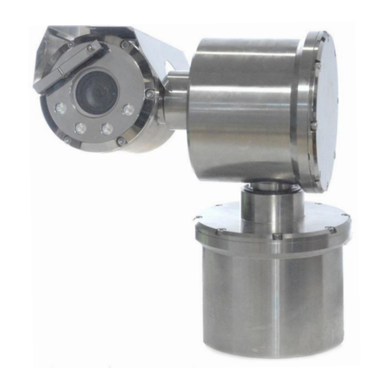
User’s Manual Overview The CC03-IP2MZ30-E Camera series is a high-performance, explosion proof video device designed to allow the movement both horizontally and vertically of the built-in camera and IR modules. It is certified for installation in industrial environments where there may be an explosive atmosphere due to gas, vapors, mists, or air or powder mixtures. -
Page 6: Model Code
➢ CSA C22.2 No. 60079-31:15 / UL 60079-31 Edition 2 ➢ CSA-C22.2 No.: 62368-1-14/UL 62368-1 Edition 1 Conditions of acceptability: ➢ Special fasteners with yield stress of at least 238 MPa shall be used. Copyright © 2019 OPTICOM INTERNATIONAL INC., All Rights Reserved. Ver 1.1... -
Page 7: System And Optional Components
CC03-IP2MZ30-E Operation Manual series User’s Manual System and Optional Components ■ Product Markings(Ex Type) CC03-IP2MX30-E Copyright © 2019 OPTICOM INTERNATIONAL INC., All Rights Reserved. Ver 1.1... -
Page 8: Safety Precautions Before Use
10. Before switching on the Camera the mechanical connection points and electrical connections of each component must been checked. 11. The national regulations for installation and assembly apply. (e.g. IEC 60079-17) Copyright © 2019 OPTICOM INTERNATIONAL INC., All Rights Reserved. Ver 1.1... -
Page 9: Product Description
Base housing - Horizontal rotation drive part, power board and video board are built in. Position control bracket - The shooting position of the camera can be fixed manually. Copyright © 2019 OPTICOM INTERNATIONAL INC., All Rights Reserved. Ver 1.1... -
Page 10: Camera Install Guide
Assembling cable gland (1) to the cable entry (3). Note: Teflon thread seal tape recommended to apply thread of cable gland Important: A certified cable gland must be used. Copyright © 2019 OPTICOM INTERNATIONAL INC., All Rights Reserved. Ver 1.1... -
Page 11: Installing Device With Wall Bracket
Use the four M8 bolts (1) supplied to fasten the camera to the bracket the direction of the arrow. Use the three M5 bolts (3) and M5 nut (4) supplied to fasten the camera to the bracket the direction of the arrow. Copyright © 2019 OPTICOM INTERNATIONAL INC., All Rights Reserved. Ver 1.1... -
Page 12: Earth Wiring Connection
Connecting earth cable to external earth bar or wall bracket as figure. Internal Earth Wiring Connection Fixed Type PTZ Type Minimum cross-sectional area of PE (Protective earthing) conductors ⚫ Copyright © 2019 OPTICOM INTERNATIONAL INC., All Rights Reserved. Ver 1.1... -
Page 13: Connection Of Device
Cross-sectional area of phase conductors, Minimum Cross-sectional area of the corresponding S (mm²) PE conductors, Sp (mm²) S ≤ 16 16 < S ≤ 35 S > 35 0.5S Connection to device ■ Copyright © 2019 OPTICOM INTERNATIONAL INC., All Rights Reserved. Ver 1.1... -
Page 14: Configuration Of The Dip-Switches
Each housing cover has a gap for separation on both sides. It can be easily removed by using two flat- head Screwdrivers. When reassembling, be sure the O-ring is correctly positioned Copyright © 2019 OPTICOM INTERNATIONAL INC., All Rights Reserved. Ver 1.1... -
Page 15: Unit Address Setting
Unit address can be set using rotary switch as shown below. Maximum address value is 255. Communication Protocol, Baud Rate, and RS mode Setting Video mode settings as below. [V OUT switch / S4-1] Protocol settings as below. [PROTOCOL switch / S4-2,3,4] Copyright © 2019 OPTICOM INTERNATIONAL INC., All Rights Reserved. Ver 1.1... - Page 16 RS-4xx communication loop mode settings as below. [LOOP switch / S6-1] Video mode and IP mode Setting IP mode settings as below. [IPSEL switch / S6-2] Resolution settings as below.[D-OUT switch / S6-2,3] Copyright © 2019 OPTICOM INTERNATIONAL INC., All Rights Reserved. Ver 1.1...
-
Page 17: Troubleshooting
In accordance with IEC 60079-19 and EN 60079-17, operators of electric plants in hazardous areas are obliged to have them serviced by qualified electricians. The warranty period is one year after purchase. Copyright © 2019 OPTICOM INTERNATIONAL INC., All Rights Reserved. Ver 1.1... -
Page 18: Specifications
Dimensions (H x W) 11.7 x 12.5 inches / 297 x 317 mm Weight 33.0 lbs (15.0 kg) Operation Temp. -40°C ~ 60°C / -40°F ~ 140°F (0~90% RH) Copyright © 2019 OPTICOM INTERNATIONAL INC., All Rights Reserved. Ver 1.1... - Page 19 CC03-IP2MZ30-E Operation Manual series User’s Manual Dimensions CC03-IP2MZ30-E Copyright © 2019 OPTICOM INTERNATIONAL INC., All Rights Reserved. Ver 1.1...
Need help?
Do you have a question about the CC03-IP2MZ30-E and is the answer not in the manual?
Questions and answers