Table of Contents
Advertisement
Quick Links
Advertisement
Table of Contents

Related Manuals for Roland Kiwitechnics KIWI-SJX


Summary of Contents for Roland Kiwitechnics KIWI-SJX
-
Page 2: Table Of Contents
Table of Contents Kiwi-SJX Features..............5 Kiwi SJX JX-10 Flow Chart..........6 Kiwi SJX MKS-70 Flow Chart..........7 Kiwi SJX JX-10 Front Panel..........8 Kiwi SJX MKS-70 Front Panel...........9 Patch and Tone Notes.............10 Patch & Tone Import Sysex Support.......10 Front Panel Description...........11 WRITE BUTTON.......................11 CANCEL BUTTON....................12 MIDI PANIC BUTTON....................12 MASTER TUNE BUTTON..................12... - Page 3 BANK 7........................19 BANK 8........................19 NUMBER PAD 0-9.....................20 ERASE SEQUENCE....................20 ..........................20 PG-800 Support..............21 PG-800........................21 Performance Control Section (JX-10 version only)..22 Pitch Bender Range....................22 Mod Wheel - LFO Trigger..................22 JX-10/MKS-70 Upgrade Notes........23 Digital Oscillators......................23 Front Panel Buttons....................23 Display........................24 Factory Presets......................24 Midi Received......................24 Midi Panic.........................24 Hold &...
- Page 4 GLOBAL PARAMETERS...................38 Global Parameters....................38 Cartridge Import.......................38 Setting up with External Devices........39 Firmware Updates............40 Tune Mode...............40 Factory Restore...............40 Upgrade install..............41 Midi Data.................52 Continuous Controllers....................53 Real Time Commands....................57 Midi Sysex Support............58 Midi Sysex Data......................59 www.kiwitechnics.com JX-SJX Upgrade User Manual v100...
-
Page 5: Kiwi-Sjx Features
Roland Tone and Patch sysex dumps into the SJX are supported • Tone imports from Oberhiem M1000, Kiwi-1000, Kiwi-30, Kiwi-8P & Roland JX-10 and JX-8P sysex dumps are supported. Quality Front Panel Button Overlays are provided with the Kiwi-SJX JX-10 and MKS-70 upgrades •... -
Page 6: Kiwi Sjx Jx-10 Flow Chart
Kiwi SJX JX-10 Flow Chart... -
Page 7: Kiwi Sjx Mks-70 Flow Chart
Kiwi SJX MKS-70 Flow Chart... -
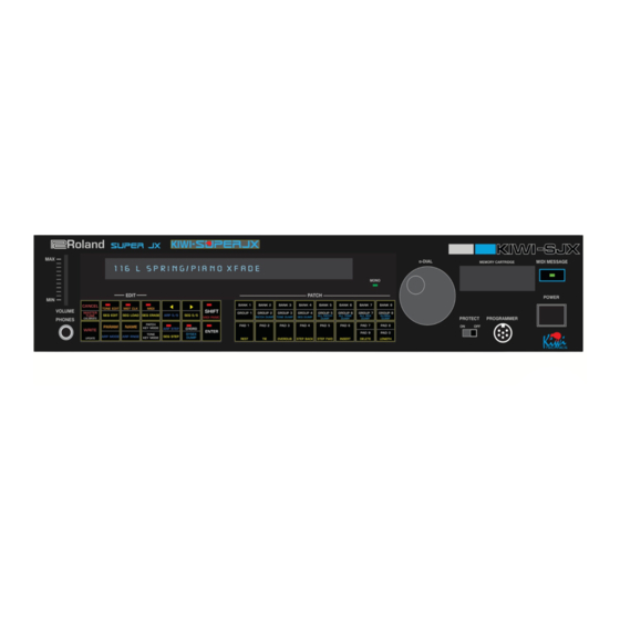
Page 8: Kiwi Sjx Jx-10 Front Panel
Kiwi SJX JX-10 Front Panel... -
Page 9: Kiwi Sjx Mks-70 Front Panel
Kiwi SJX MKS-70 Front Panel... -
Page 10: Patch And Tone Notes
The KiwiSJX upgrade supports loading Roland format sysex dumps. To fully load in a Roland MKS-70/JX-10 Patch & Tone dump this must be sent to the KiwiSJX twice. The reason for this is the Roland format has the Patch data before the Tone data. -
Page 11: Front Panel Description
Front Panel Description The Kiwi-SJX front panels differ from the original JX-10 and MKS-70 in a number of ways and the Kiwi-SJX Upgrade redefines many of the buttons of this synth. Buttons have been assigned new functions and others now operate differently. Button overlays with the new button functions are supplied with the upgrade. -
Page 12: Cancel Button
CANCEL BUTTON The CANCEL button will exit most In the MKS-70 this button is shared operations. The Arp & Seq Step Timing with the Master Tune button. button edits will need to be exited via the same Step Timing button. MIDI PANIC The MIDI PANIC will stop all sound from In the MKS-70 version of the Kiwi-SJX... -
Page 13: Midi Button
MIDI BUTTON The MIDI button allows the synth global 5) Program Change Enable – There midi options to be set. These will be are four possible options. memorised and retained when the power – No program change is sent or is turned off. -
Page 14: Parameter Button
PARAMETER The PARAMETER button allows editing of Every parameter will have an ID. For all the parameters for a Tone and Patch example the VCF cutoff looks like 211 BUTTON as well as some of the Global Parameters. (G2 B1 T1). To get to this parameter A parameter is made up of three sections. -
Page 15: Tone Key Mode Button
TONE KEY MODE The TONE KEY MODE button will select POLY DUAL – Each note played will one of five Tone Key Mode types using select two sounding voices. A BUTTON the Alpha Dial. Changes will only apply to maximum of 3 notes can be played. the currently selected voice board. -
Page 16: Tap Timer
TAP TIMER The internal clock rate can be set by This option is not available in the using this button. Tapping this button in MKS-70 version of the Kiwi-SJX. time with the beat will set the internal clock to this rate. The first tap will display “TIMING TAP”... -
Page 17: Group 1-8
GROUP 1-8 In the JX-10 version these buttons will When the Kiwi-SJX is in Tone Edit select Group 1 to Group 8 Patches under Mode These buttons will select the normal play mode. The Patch will current Tone Group (1-8) for Loading immediately load. -
Page 18: Bank 3
BANK 3 This button will select Bank 3 Patches When the Kiwi-SJX is in Tone Edit under normal play mode. The Patch will Mode This buttons will select the immediately load. Each Bank # has 8 current Tone Bank 3 for Loading or Edit Letter “/”... -
Page 19: Bank 6
BANK 6 This button will select Bank 6 Patches When the Kiwi-SJX is in Tone Edit under normal play mode. The Patch will Mode This buttons will select the immediately load. Each Bank # has 8 current Tone Bank 6 for Loading or Edit Letter “>”... -
Page 20: Number Pad 0-9
NUMBER PAD 0-9 Number buttons 1-8 are used for loading When writing a Patch or Tone these and saving Patches and Tones. Number buttons will select the Patch or Tone buttons 0 & 9 are only used for selecting number that the Patch or Tone will be editing parameters. -
Page 21: Pg-800 Support
PG-800 Support PG-800 The PG-800 is supported by the Kiwi- PG-800 edits will only effect the SJX. Because of the nature of the currently selected voice board. The PG-800 interface the edits made this voice board can be selected and way are slow and can have audible changed using the Lower &... -
Page 22: Performance Control Section (Jx-10 Version Only)
Performance Control Section (JX-10 version only) This four position switch allows you to Note - This Switch settings is saved Pitch Bender Range change the range of the Bend lever. In with the Tone. the original JX-10 these ranges were 2, 3, 5 &... -
Page 23: Jx-10/Mks-70 Upgrade Notes
JX-10/MKS-70 Upgrade Notes Digital Oscillators The JX-10 and MKS-70 Synthesizers Another 'feature' of this type of use programmable dividers from a oscillator is with smooth changes single master oscillator to generate between notes audible stepping the pitch of the notes. While this will increase higher... -
Page 24: Display
Factory Presets The factory patch and tone presets in The SJX supports the Roland the SJX are all a blank patch and format of Patch and Tone sysex tone. To restore the factory Patches dumps. -
Page 25: Edit Buffer Compare
Edit Buffer Compare Whenever the edit buffer does not To retain these changes when the match the saved Patch or Tone Patch or Tone is changed or the showing on the display the three JX-10 is powered off the Patch decimal points on the G/B/T part of must be written to memory. -
Page 26: Sequencer
Sequencer JX-10 Upgrade contains SEQ LOAD polyphonic 6 track sequencer that capacity step This button followed by a Number automatic playing. pad button (1-8 only) is used to select and load a sequence. The clock for the Sequencer is There are 8 Sequence memories and always the Master Clock and this can only one of these can be selected at be divided by one of 13 different... -
Page 27: Sequencer Writing / Editing
Sequencer Writing / Editing The memory protect switch (on the (3) By playing the keyboard and rear of the JX-10 or front of the MKS- using the Tie button and Rest 70) must be set to Off to Edit or buttons, write steps one after create a sequence in memory. -
Page 28: C) Playing
C) Playing * If you stop the Sequence part Load Sequence way through and then restart it A Sequence can be loaded in two the data will start from the ways. A Sequence is loaded manually beginning. by pressing SEQ LOAD followed by a Number Button 1-8. -
Page 29: Arpeggiator
Arpeggiator The KiwiTechnics Kiwi-SJX Upgrade Canceling Arpeggiator Mode. has a built in Arpeggiator that can be Arpeggiator mode can be stopped by applied to any sound. pressing the ARP button. The light on the ARP button will go out. Arpeggiator Mode is started and stopped by pressing the ARP Button. -
Page 30: Chord Mode
Chord Mode A Chord is set by playing the Chord As only one chord can be played and then pressing and releasing the at a time the keys played have last CHORD Button while the keys of the note priority. chord are being held. -
Page 31: Parameter Editing
Parameter Editing Parameter editing is done in two Parameter numbers are in three parts different sections in the Kiwi-SJX. A and contain a 'G', a 'B' and a 'T' number Patch can be edited and a Library and will look like 211 for VCF Cutoff for Tone can be edited. -
Page 32: Dco Parameters
DCO Parameters 110 – DCO 1 Range Options are 16', 8', 4' or 2' 121 – DCO 2 Range (For 32' or 1' use DCO Tune) 111 – DCO 1 Wave Options are Saw, Pulse, Square or 122 – DCO 2 Wave Random 112 –... -
Page 33: Lfo Parameters
LFO Parameters 219 – LFO 1 Wave Options are Sine, Triangle, Saw, Rev Saw, Square, Random 220 – LFO 1 Rate Range is 0-127 221 – LFO 1 Delay Range is 0-127 222 – LFO 1 Mode Options are Normal or Plus Normal will raise and lower parameter being edited and Plus will only raise the parameter being edited... -
Page 34: Modulation Matrix
Modulation Matrix 310 – Matrix 0 - 9 Source Matrix Source options are 313, 316, 319, 322, 325, 328, 331, 0 - Off 334, 337 1 - Bend Up 2 - Bend Down 3 - Bend Full 4 – Midi Mod or Mod Wheel 5 –... -
Page 35: Env Dadsr
312 – Matrix 0 - 9 Destination Matrix Destination options are 315, 318, 321, 324, 327, 330, 333, 0 - Off 336, 339 1 - DCO1 Freq 2 - DCO2 Freq 3 - All DCO Freq 4 - DCO1 Wave 5 - DCO1 Range 6 –... -
Page 36: Tone Voice Parameters
Tone Voice 425 - Voice Keying Mode Voice Assign Mode selects the way the tone voices are assigned to notes Parameters played Options are Poly Single – 6 notes trigger 6 voices Poly Dual – 3 notes max trigger 2 voices each Poly Triple –... -
Page 37: Patch Parameters
Patch Parameters 429 – Patch Key Mode Options are WHOLE – The JX-10 acts like a single 12 voice synth with the Lower Tone in the Patch sounding on both voice boards. Upper Tone edits will be stored but will have no effect on the sound. -
Page 38: Global Parameters
2 = Vecoven PW Mod fitted Cartridge Import 439 - Cartridge Import This will import Patches and Tones from a Roland Cartridge when WRITE is pressed. Be careful with this as imported Patches and tones will be copied into the currently selected... -
Page 39: Setting Up With External Devices
Setting up with External Devices Midi Notes Hold Pedal Midi Through should be used if Any pedal that shorts the tip to multiple units are being used on the ground when pressed or open can midi chain to reduce delays. While be used. -
Page 40: Firmware Updates
Firmware Updates Firmware Updates To start the firmware upload in the JX- 10 press and hold the MIDI PANIC button as you power on the Synth. Firmware updates in the Kiwi-SJX more involved than other To start the firmware upload in the Kiwitechnics Upgrades due to the MKS-70 press and hold the WRITE fact that there are three cpus and... -
Page 41: Upgrade Install
If you are in any doubt at all or do not understand any part of this document then have this work done by a professional. The KiwiTechnics Kiwi-SJX Upgrade must be installed by a competent technician with the correct tools or damage to your JX-10 or MKS-70 can occur. KiwiTechnics will not be responsible for damage done to your precious JX-10 or MKS-70 if this upgrade is not fitted correctly. - Page 42 UNPLUG THE JX-10! UNPLUG THE JX-10! There are dangerous voltages inside the unit and it must not be opened until the power plug is removed from the power supply. Three 40 pin cpus, Two 40 pin I/O chips, two 16 pin A to D chips and other components need to be removed and replaced with five 40 pins sockets, some links and some resistors which are supplied with the KiwiTechnics JX-10/MKS-70 Upgrades.
- Page 43 Step 1) Opening the MKS-70. Remove the rack mounts if fitted. These can have 3 or 4 countersunk bolts each and shaped spring washers. Put these to one side and do not lose the screws or washers as these are hard to replace. Remove the small screw at the top center rear and then turn over the MKS-70 and remove the three screws located at each side that are holding the top part of the case on.
- Page 44 Step 3) Desolder the listed ICs, resistors and transistor and fit the supplied 40 pin IC sockets, resistors and links on the cpu board and both voice boards. It is very important that this step is done correctly. On the top side of the voice boards underneath the ICs (Integrated Circuits) that need to be removed are some fine tracks that will be damaged and difficult to repair if all the solder is not removed correctly.
- Page 45 Program ROM IC6 can also be removed if it is socketed as it is not used in the upgrade. If this is soldered in it can be left. This picture shows all the parts removed. JX-10 CPU Board In the JX-10 fit the 16k resistors. and 10k resistors, the 40 pin IC socket and the R34 Link.
- Page 46 Here is a close up of the IC21 links in the JX-10 and the 16k resistors fitted to R43 & R44 positions and a close up of the RA7 10k resistors for the MKS-70 and the JX-10. Link R34 – This is the resistor removed during step 1 and this needs to be replaced with a link in both the JX-10 &...
- Page 47 JX-10/MKS-70 CPU & Voice Boards There are two of these and they are the same. Only the fitting of one board has been detailed but both voice boards need to have the same work done. Only the JX-10 Upper voice board has the shield fitted as pictured. 1) Remove IC10 and IC14.
- Page 48 Fit the two 40 Pin Sockets into IC10 & IC14 locations. Fit the KiwiSJX Voice Board. There are two different KiwiSJX Voice Daughter boards. One has a link fitted between 1 & 2 on the option jumper point on the board and is marked 'Upper'. This must be placed in the UPPER Voice board in order to function correctly. Only the Upper voice board is connected to the Midi Out so if the wrong KiwiSJX Voice board is put into the wrong SJX Voice board the midi out will not work.
- Page 49 Refitting the JX-10/MKS-70 CPU & Voice Boards The process of refitting the boards to the JX-10 & MKS-70 is the reverse of removing them. In the JX-10 the shield need to be refitted to the right Upper voice board. In the MKS-70 the cpu must be fitted first followed by the Upper voice board and the Lower voice board is fitted last. In the JX-10 The 4 plugs from the keyboard scan lines need to be moved and plugged into the KiwiSJX cpu daughter board.
- Page 50 Upgrade Labels The Kiwitechnics Kiwi-SJX comes with button labels that are placed over the existing front panel buttons on the JX-10 or MKS-70. The following buttons are relabeled on the JX-10 Button Name Label Name WRITE Button WRITE/Calibrate CART>INT MIDI PANIC/Load INT>CART...
- Page 51 The Kiwitechnics Kiwi-SJX MKS-70 version comes with button labels that are placed over all the existing front panel buttons on the MKS-70. The following buttons are relabeled on the MKS-70 Button Name Label Name MASTER TUNE Button CANCEL/MASTER TUNE/Calibrate PATCH...
-
Page 52: Midi Data
Midi Data Function Transmitted Recognized Notes Basic Channel 1-16 1-16 If Omni selected the KiwiSJX will recognize any midi channel Note Number 24(C1)-108(C8) 0-127 Notes that are received outside the KiwiSJX range of 24-108 are transposed to the nearest octave within range. Mode Voice Modes need to be changed using Midi Control or Sysex commands... -
Page 53: Continuous Controllers
Continuous Controllers Note – All Tone MidiCC commands will be performed on the Currently Selected Lower or Upper Voice only Continuous Controllers Second Third Notes Bank Select MSB $00 (00) $00-$01 0=Bank Selection, 1=Not Used, 2=Seq Selection Used in conjunction with CC32 Bank Select LSB Modulation Wheel Level $01 (01) $00-$7f (0-127) - Page 54 Continuous Controllers Note – All Tone MidiCC commands will be performed on the Currently Selected Lower or Upper Voice only ENV 3 Delay $29 (41) $00-$7f (0-127) ENV 3 Attack $2a (42) $00-$7f (0-127) ENV 3 Decay $2b (43) $00-$7f (0-127) ENV 3 Sustain $2c (44) $00-$7f (0-127)
- Page 55 Continuous Controllers Note – All Tone MidiCC commands will be performed on the Currently Selected Lower or Upper Voice only DCO2 LFO Source $47 (71) $00-$1f (0-15) LFO 1 $20-$2f (32-47) LFO 2 $40-$4f (64-79) LFO 3 DCO2 ENV Source $48 (72) $00-$1f (0-31) ENV 1...
- Page 56 Continuous Controllers Note – All Tone MidiCC commands will be performed on the Currently Selected Lower or Upper Voice only Arpeggiator Mode $56 (86) $yy = $00-$0f (0-15) PATCH PARAMETER $10-$1f (16-31) Down $20-$2f (32-47) Up & Down $30-$3f (48-63) Random $40-$7f (64-127) As Played...
-
Page 57: Real Time Commands
Continuous Controllers Note – All Tone MidiCC commands will be performed on the Currently Selected Lower or Upper Voice only RPN Data LSB $64 (100) Not Supported RPN Data MSB $65 (101) Not Supported Voice Mode Envelopes $68 (104) $00-$3f (0-63) Staccato $40-$7f (64-127) Legato... -
Page 58: Midi Sysex Support
Midi Sysex Support Function Transmitted Recognized Notes Basic ID 1-16 1-16 Set using Device ID in Global Variable Load Dump Function Device Enquiry $F0 $7E <MIDI CHANNEL> $06 $01 $F7 Device Enquiry Response $F0 Sysex Start Non Real time reply Midi Channel (0-15) Enquiry Message Enquiry Reply... -
Page 59: Midi Sysex Data
Midi Sysex Data Notes $nn = Hexadecimal Data - Decimal data is in Brackets e.g. $0a (10) Sysex Header Sysex Start $00 $21 $16 Kiwitechnics Manufacturers ID Kiwitechnics Family ID Kiwitechnics JX-10/MKS-70 ID Device ID ($00-$0f) (JX-10/MKS-70 Device ID 1-16) – Not currently used – Set to 00 Command ID (see table 1.0) Request Global Dump Transmit/Receive Global Dump... - Page 60 Table 1.0 Command ID Data Byte Data Type Data Details Byte details 7 ------- 0 $01 (1) Request Global Dump No Data JX-10/MKS-70 transmits a $02 (2) command $02 (2) Transmit or Receive Global $00 (0) = Midi Channel In 000yxxxx xxxx = 0-15 for midi channel 1-16 set for Omni...
- Page 61 Table 1.0 Command ID Data Byte Data Type Data Details Byte details 7 ------- 0 $0b (11) = Int Clock RateLo 0000yyyy This byte is sent as two nibbles which are combined to make single 8 bit command. 0000xxxx + 0000yyyy = xxxxyyyy 0-255 = 5-300 BPM $0c (12) = Memory Protect 0000000z...
- Page 62 Table 1.0 Command ID Data Byte Data Type Data Details Byte details 7 ------- 0 $14 (20)=DCO1 Wave/Range 0000zzxx xx = DCO1 Range 00=16' 01=8' 10=4' 11=2' zz = DCO1 Wave 00=Saw 01=Pulse 10=Square 11=Noise $15 (21)=DCO1 Coarse Tune 0xxxxxxx x=0-48 = -12 →...
- Page 63 Table 1.0 Command ID Data Byte Data Type Data Details Byte details 7 ------- 0 $20 (32)=DCO2 Initial ENV Amount 0xxxxxxx x = Range $00-$7e (-63 → 0 → +63) - ($7f=$7e) $21 (33)=DCO1 Initial PW Amount 0xxxxxxx x = Range $00-$7f (0-127) $22 (34)=DCO1 Initial PWM Amount 0xxxxxxx x = Range $00-$7f (0-127)
- Page 64 Table 1.0 Command ID Data Byte Data Type Data Details Byte details 7 ------- 0 $37 (55)=VCA Control 000yy0zz zz = VCAENV(00=Gate,01=Env1,10=Env2,11=Env3) yy = VCALFO(00=LFO1,01=LFO2,10=LFO3) $38 (56)=VCA DYN Amount 0xxxxxxx x = Range $00-$7f (0-127) $39 (57)=Matrix 0 Source 000xxxxx x = 0-30 –...
- Page 65 Table 1.0 Command ID Data Byte Data Type Data Details Byte details 7 ------- 0 $52 (82)=Matrix 8 Level 0xxxxxxx x = Range $00-$7e (-63 → 0 → +63) - ($7f=$7e) $53 (83)=Matrix 8 Destination 000xxxxx x = 0-40 – See Table 3 $54 (84)=Matrix 9 Source 000xxxxx x = 0-30 –...
- Page 66 Table 1.0 Command ID Data Byte Data Type Data Details Byte details 7 ------- 0 $69 (105)=LFO 1 Control 00xxxxxy 0=Mode (0=Normal,1=Plus) xxxxx= 00000-Free Running 00001-Sync Two Notes (192 Clocks/Step) 00010-Sync Dotted Whole Note (144 Clocks/Step) 00011-Sync Whole Note (96 Clocks/Step) 00100-Sync Dotted Half Note (72 Clocks/Step) 00101-Sync Half Note (48 Clocks/Step) 00110-Sync Dotted 1/4 Note (36 Clocks/Step)
- Page 67 Table 1.0 Command ID Data Byte Data Type Data Details Byte details 7 ------- 0 $6d (109)=LFO 2 Control 00xxxxxy 0=Mode (0=Normal,1=Plus) xxxxx= 00000-Free Running 00001-Sync Two Notes (192 Clocks/Step) 00010-Sync Dotted Whole Note (144 Clocks/Step) 00011-Sync Whole Note (96 Clocks/Step) 00100-Sync Dotted Half Note (72 Clocks/Step) 00101-Sync Half Note (48 Clocks/Step) 00110-Sync Dotted 1/4 Note (36 Clocks/Step)
- Page 68 Table 1.0 Command ID Data Byte Data Type Data Details Byte details 7 ------- 0 $71 (113)=LFO 3 Control 00xxxxxy 0=Mode (0=Normal,1=Plus) xxxxx= 00000-Free Running 00001-Sync Two Notes (192 Clocks/Step) 00010-Sync Dotted Whole Note (144 Clocks/Step) 00011-Sync Whole Note (96 Clocks/Step) 00100-Sync Dotted Half Note (72 Clocks/Step) 00101-Sync Half Note (48 Clocks/Step) 00110-Sync Dotted 1/4 Note (36 Clocks/Step)
- Page 69 Table 1.0 Command ID Data Byte Data Type Data Details Byte details 7 ------- 0 $06 (6) Transmit/Receive Library Bank Number 000000xx xx = 0 for Tones 1-128 1 for Tones 129-256 Tone Dump 2 for Tones 257-384 3 for Tones 385-512 Bank + Tone + 118 data bytes WARNING! This command will overwrite Tone Number...
- Page 70 Table 1.0 Command ID Data Byte Data Type Data Details Byte details 7 ------- 0 $0d (13) Request Library Edit $00 (0) - Tone Parameter Number 0000xxxx Data Offset Hi Nibble Use Data Position for Parameter Number Buffer Tone Parameter Data format the same as $04 e.g.
- Page 71 Table 1.0 Command ID Data Byte Data Type Data Details Byte details 7 ------- 0 $02 (2) - Parameter Value (Lo) 0yyyyyyy Hi & Lo are combined to make single 12 bit command. 000xxxxx + 0yyyyyyy = 0000xxxx xyyyyyyy $1c (28) Request Patch Edit Buffer JX-10/MKS-70 transmits a $12 (18) command Dump $1d (29) Transmit or Receive Patch...
- Page 72 Table 1.0 Command ID Data Byte Data Type Data Details Byte details 7 ------- 0 $1a (26)=Patch Clock TempoHi 0000xxxx If this is nonzero it will replace the internal Clock speed with this temporary value. If this value is zero the internal clock will remain unchanged.
- Page 73 Table 1.0 Command ID Data Byte Data Type Data Details Byte details 7 ------- 0 $35 (53)=Lower DCO1 Wave/Range 0000zzxx xx = DCO1 Range 00=16' 01=8' 10=4' 11=2' zz = DCO1 Wave 00=Saw 01=Pulse 10=Square 11=Noise $36 (54)=Lower DCO1 Coarse Tune 0xxxxxxx x=0-48 = -12 →...
- Page 74 Table 1.0 Command ID Data Byte Data Type Data Details Byte details 7 ------- 0 $3f (63)=Lower DCO2 Fine Tune 0xxxxxxx x=0-100 +- 50 Cents and zero 0-49 is shifted down 50 is not shifted 51-100 is shifted up $40 (64)=Lower DCO2 Initial LFO 0xxxxxxx x = Range $00-$7f (0-127) Amount...
- Page 75 Table 1.0 Command ID Data Byte Data Type Data Details Byte details 7 ------- 0 $50 (80)=Lower VCF Initial 0yyyyyyy Hi & Lo are combined to make single 12 bit command. Resonance Lo 000xxxxx + 0yyyyyyy = 0000xxxx xyyyyyyy x = Range $0-$fff (0-4095) $51 (81)=Lower VCF Initial LFO 0xxxxxxx x = Range $00-$7e (-63 →...
- Page 76 Table 1.0 Command ID Data Byte Data Type Data Details Byte details 7 ------- 0 $66 (102)=Lower Matrix 4 Source 000xxxxx x = 0-30 – See Table 1 $67 (103)=Lower Matrix 4 Level 0xxxxxxx x = Range $00-$7e (-63 → 0 → +63) - ($7f=$7e) $68 (104)=Lower Matrix 4 000xxxxx x = 0-40 –...
- Page 77 Table 1.0 Command ID Data Byte Data Type Data Details Byte details 7 ------- 0 $7e (126)=Lower ENV2 Attack 0xxxxxxx x = Range $00-$7f (0-127) $7f (127)=Lower ENV2 Decay 0xxxxxxx x = Range $00-$7f (0-127) $80 (128)=Lower ENV2 Sustain 0xxxxxxx x = Range $00-$7f (0-127) $81 (129)=Lower ENV2 Release 0xxxxxxx...
- Page 78 Table 1.0 Command ID Data Byte Data Type Data Details Byte details 7 ------- 0 $8b (139)=Lower LFO 2 Wave 000000xxx xxx = 000=Sine 001=Triangle 010=Square 011=Saw 100=Reverse Saw 101=Random 110=Fast Random $8c (140)=Lower LFO 2 Rate 0xxxxxxx x = Range $00-$7f (0-127) $8d (141)=Lower LFO 2 Delay 0xxxxxxx x = Range $00-$7f (0-127)
- Page 79 Table 1.0 Command ID Data Byte Data Type Data Details Byte details 7 ------- 0 $92 (146)=Lower LFO 3 Control 00xxxxxy 0=Mode (0=Normal,1=Plus) xxxxx= 00000-Free Running 00001-Sync Two Notes (192 Clocks/Step) 00010-Sync Dotted Whole Note (144 Clocks/Step) 00011-Sync Whole Note (96 Clocks/Step) 00100-Sync Dotted Half Note (72 Clocks/Step) 00101-Sync Half Note (48 Clocks/Step) 00110-Sync Dotted 1/4 Note (36 Clocks/Step)
- Page 80 Table 1.0 Command ID Data Byte Data Type Data Details Byte details 7 ------- 0 $ac (172)=Upper DCO1 Coarse Tune 0xxxxxxx x=0-48 = -12 → + 12 notes in half semitone steps $ad (173)=Upper DCO1 Initial LFO 0xxxxxxx x = Range $00-$7f (0-127) Amount $ae (174)=Upper DCO1 Initial ENV 0xxxxxxx...
- Page 81 Table 1.0 Command ID Data Byte Data Type Data Details Byte details 7 ------- 0 $b9 (185)=Upper DCO1 Initial PWM 0xxxxxxx x = Range $00-$7f (0-127) Amount $ba (186)=Upper DCO2 DYN Amount 0xxxxxxx x = Range $00-$7f (0-127) $bb (187)=Upper DCO2 Control 0ww0yyzz zz = DCO1Env(00=Env1,01=Env2,10=Env3)
- Page 82 Table 1.0 Command ID Data Byte Data Type Data Details Byte details 7 ------- 0 $cb (203)=Upper VCF Control 0000yyzz zz = VCFEnv(00=Env1,01=Env2,10=Env3) yy = VCFLFO(00=LFO1,01=LFO2,10=LFO3) $cc (204)=Upper VCA Initial Level 0xxxxxxx x = Range $00-$7f (0-127) $cd (205)=Upper VCA Initial LFO 0xxxxxxx x = Range $00-$7e (-63 →...
- Page 83 Table 1.0 Command ID Data Byte Data Type Data Details Byte details 7 ------- 0 $e1 (225)=Upper Matrix 5 000xxxxx x = 0-40 – See Table 3 Destination $e2 (226)=Upper Matrix 6 Source 000xxxxx x = 0-30 – See Table 1 $e3 (227)=Upper Matrix 6 Level 0xxxxxxx x = Range $00-$7e (-63 →...
- Page 84 Table 1.0 Command ID Data Byte Data Type Data Details Byte details 7 ------- 0 $fa (250)=Upper ENV3 Decay 0xxxxxxx x = Range $00-$7f (0-127) $fb (251)=Upper ENV3 Sustain 0xxxxxxx x = Range $00-$7f (0-127) $fc (252)=Upper ENV3 Release 0xxxxxxx x = Range $00-$7f (0-127) $fd (253)=Upper LFO 1 Wave 000000xxx...
- Page 85 Table 1.0 Command ID Data Byte Data Type Data Details Byte details 7 ------- 0 $104 (260)=Upper LFO 2 Control 00xxxxxy 0=Mode (0=Normal,1=Plus) xxxxx= 00000-Free Running 00001-Sync Two Notes (192 Clocks/Step) 00010-Sync Dotted Whole Note (144 Clocks/Step) 00011-Sync Whole Note (96 Clocks/Step) 00100-Sync Dotted Half Note (72 Clocks/Step) 00101-Sync Half Note (48 Clocks/Step) 00110-Sync Dotted 1/4 Note (36 Clocks/Step)
- Page 86 Table 1.0 Command ID Data Byte Data Type Data Details Byte details 7 ------- 0 $108 (264)=Upper LFO 3 Control 00xxxxxy 0=Mode (0=Normal,1=Plus) xxxxx= 00000-Free Running 00001-Sync Two Notes (192 Clocks/Step) 00010-Sync Dotted Whole Note (144 Clocks/Step) 00011-Sync Whole Note (96 Clocks/Step) 00100-Sync Dotted Half Note (72 Clocks/Step) 00101-Sync Half Note (48 Clocks/Step) 00110-Sync Dotted 1/4 Note (36 Clocks/Step)
- Page 87 Table 1.0 Command ID Data Byte Data Type Data Details Byte details 7 ------- 0 $1f (31) Transmit or Receive Patch Bank Number 000000xx xx = 0 for Patch 1-128 1 for Patch 129-256 Dump 2 for Patch 257-384 3 for Patch 385-512 2 bytes Bank/Patch + 269 data bytes WARNING! This command will overwrite...
- Page 88 Table 2 Matrix Source Types Matrix Destination Types Bend Up DCO1 Freq Bend Down DCO2 Freq Bend Full All DCO Freq Midi or Internal Mod DCO1 Wave Key Down Velocity DCO1 Range Key Up Velocity DCO1 LFO Level Key Note DCO1 ENV Level Edit Slider/Rear Input C1 DCO1 PW Level...
- Page 89 www.kiwitechnics.com JX-SJX Upgrade User Manual v100...
Need help?
Do you have a question about the Kiwitechnics KIWI-SJX and is the answer not in the manual?
Questions and answers