Advertisement
Quick Links
APOLPERG [A5 4page instructions]
15/9/17
STEP 5
The Upper Leg Braces (4) must
now be fitted. These are fitted at
UPON COMPLETION, SCREW THE
alternate intervals between the
FINIAL (2) INTO THE TOP OF THE
legs.
Using a rigid piece of timber, mark
off 100cm from where the
bottom edge of the top of the Leg
is attached to the Centre Block to
the top edge of the Leg.
The Brace should be attached to
the Leg such that the Brace is as
shown in fig.5, parallel to the
ground. Fix with two screws (b) in
either end.
STEP 6
The Lower Leg Braces (5) should
now be fitted in between the legs
without top Braces.
Determine the height where
the Braces will be fixed. This
may be any distance between
45cm-50cm
TIP:
Cut two pieces of timber
to the desired height and place
against the leg to support the
Brace whilst fixing.
Screw all four Braces in place.
Fix the Angle Brackets (d) at the
centre of the Brace as shown in
fig.6 to support each of the
Braces. This will allow them to be
used as seats if preferred.
NOTE
All timber is subject to slight
b
movement so always erect your
structure first before measuring
your base.
AFTERCARE
To ensure longevity of your
structure it is recommended that
it is treated with a wood
preservative on a yearly basis.
The manufacturer reserves the
right to alter specifications as
necessary.
AFTERCARE
To ensure longevity of your structure it is recommended that it is treated with a wood preservative on a yearly basis.
13:10
Page 1
2
CENTRE BLOCK (1)
3
1
b
3
5
b
b
SCREW THROUGH THE
LEGS INTO THE UPPER
AND LOWER BRACES
b
5
b
approx.
45cm - 50cm
5
3
FOR EXTRA STRENGTH
ADD THE TWO ANGLE BRACKETS
d
(d) IN THE CENTRES OF EACH
BRACE WITH SCREWS (b)
b
d
b
5
(fig.6)
3
1
3
4
(fig.5)
3
©2015 Grange Fencing Ltd All rights reserved.
In line with the Company's policy of
continuous product development, the right
is reserved to change and improve product
design without prior notice.
All products and related emblems featured are
trademarks of Grange Fencing Ltd.
www.grangefen.co.uk
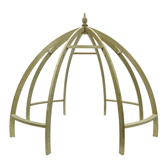
APOLLO PERGOLA
APOLPERG - 261cm [H] x 347cm [DIA.]
Self-Assembly required
PLAN
347cm
TOP VIEW
Home Delivery available
SIDE VIEW
347cm
Advertisement

Related Manuals for Grange Apollo


Summary of Contents for Grange Apollo
- Page 1 (fig.6) 347cm SIDE VIEW necessary. 347cm TOP VIEW ©2015 Grange Fencing Ltd All rights reserved. In line with the Company’s policy of continuous product development, the right is reserved to change and improve product design without prior notice. AFTERCARE All products and related emblems featured are To ensure longevity of your structure it is recommended that it is treated with a wood preservative on a yearly basis.
- Page 2 APOLPERG [A5 4page instructions] 15/9/17 13:10 Page 2 Thank you for choosing this garden structure from Grange. In order APOLLO to gain the most benefit from it please read the following instructions carefully. ‘FOOTPRINT’ TOOLS REQUIRED (Not Supplied) POWER DRILL...
Need help?
Do you have a question about the Apollo and is the answer not in the manual?
Questions and answers