Advertisement
Quick Links
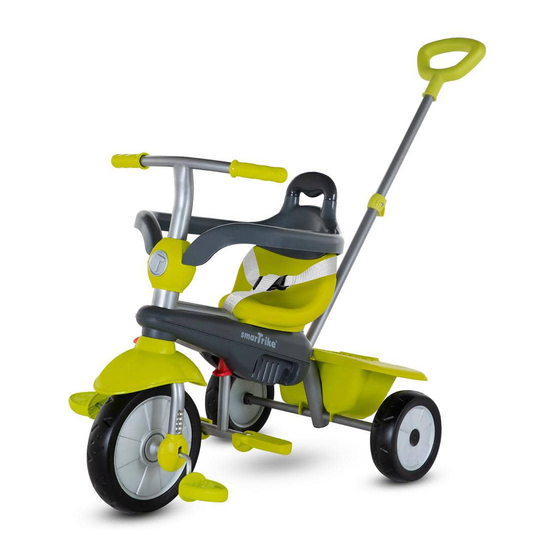
Thank you for buying smarTrike,
If you have any assembly issues or are missing
a part, please call us for assistance. Our
smarTrike® assembly experts will assist you.
DO NOT RETURN TO THE STORE
If you are experiencing problems with this
product, please call our HELP LINE.
UK: +44-2035148561
9:30am – 5:00pm Monday to Friday
www.smarTrike.com
Not Bank Holidays or weekends.
You can also email us: help@mookie.co.uk
for assistance and advice.
607/609/615/617/319/645/665
USA: 1-855-SMTRIKE
(1-855-768-7453)
607/609
615
645
617
319 A
319 B
665 A
665 B
-1-
Advertisement

Subscribe to Our Youtube Channel
Related Manuals for SmartTrike 607


Summary of Contents for SmartTrike 607
- Page 1 HELP LINE. UK: +44-2035148561 9:30am – 5:00pm Monday to Friday www.smarTrike.com Not Bank Holidays or weekends. You can also email us: help@mookie.co.uk for assistance and advice. 607/609/615/617/319/645/665 USA: 1-855-SMTRIKE (1-855-768-7453) 607/609 319 A 319 B 665 A...
- Page 2 607/609/615/617/319/645/665 607100 607130 607120 607210 607150 607220 607110 607200 607141 607190 607140 665140 617140 607/609 615/645/319 665160 607160 607/609 319/665 615/617/645 615170 665170 615/645 319/665 665410 615360 615310 607/609 319B 615/645/617 645/665B...
- Page 3 Step 1 Parts needed to complete this section Place a washer (J), a wheel (B) and another washer (J) on the back axle. Firmly insert black plug (K) into axle opening, as shown. Align spring lock with dropout hole in axle and push firmly into position, until piece "clicks"...
- Page 4 Step 2 Parts needed to complete this section Insert part D into part Insert part E into the C all the way through body of the trike all the the hole (as shown) the hole. way through the hole.
- Page 5 Step 3 Parts needed to complete this section Push the apple rmly down to ly down to Push the apple firmly down to insert, insert, slightly turn until you insert, slightl slightly turn until you hear a "click". Make " sure white connector is not visible.
- Page 6 Step 4 Parts needed to complete this section By using the Phillips screwdriver Push basket (F) firmly onto (L), remove screw by turning rear axle until it "clicks" into counter clockwise. position (see 1 & 2). Attach basket firmly to vertical frame, use removed screw and turn clockwise until secured.
- Page 7 Step 5 Parts needed to complete this section 319/665 319/665 Take the seat (G), push the screw through the By using the "Allen" key (L), remove seat hole. Screw into the most rear facing screw by turning counter clockwise. hole and firmly tighten with Allen key (L). With little force, push part H into the apple's holes until you hear a "click".
- Page 8 Step 6-7 Parts needed to complete this section WARNING: This product should be used on safe ground, it should not be used near steps, slopes, roadways, public highways or wet areas. WARNING: Ensure safety pin is inserted correctly and secured. Insert the parent handle (I) into the retaining Remove the securing pin with hole on rear of trike.
- Page 9 607/609 WARNING: Nut must be inserted correctly and secured. Insert part N1 into part I. Use Phillips screwdriver (L) Keep the nut in place, remove Align the hole of part I with to attach the screw to the the screw from part I by the correct hole in part N1.
- Page 10 615 / 645 WARNING: Nut must be inserted correctly and secured. Use Phillips screwdriver (L) Insert part N1 into part P1 by Remove the screw from part I to attach the screw to the pressing the two buttons. Slide by turning counter clockwise. nut.
- Page 11 Insert the bar into part N3. Align Remove the screw from part Wrap hook and loop straps the hole of the bar with a hole in N3 by turning counter around the parent handle. part N3. Use Phillips screwdriver clockwise. (L) to attach the screw to the nut.
- Page 12 319 B WARNING: Nut must be inserted correctly and secured. Insert part N1 into part I. Align the Insert part O2 into the Keep the nut in place, remove hole of part I with the correct hole in the safetybar, until you the screw from part I by part N1.
- Page 13 WARNING: Nut must be inserted correctly and secured. Insert part N2 into part I. Align the Insert part O2 into the Keep the nut in place, remove hole of part I with the correct hole in the safetybar, until you the screw from part I by part N2.
- Page 14 Bag Step Parts needed to complete this section 319 A 319 B 665 B Max. load of basket 2.2 lb / 1 kg. Attach handles of the bag (R) Pull the elastic bands around to parent handle hook. the sides of the basket. 665 B Wrap hook and loop strap around the parent handle.
-
Page 15: Parent Control
Parent Control 10M+ When the clutch is pulled away from the wheel there is no pedal control and the wheel is in a free-wheel position Child Control For the 24+ months stage, Push release button to place it fold up left and right footrest. back into frame. - Page 16 When the clutch is pushed closed and aligned with the front wheel, child has pedal control. 607/609 615/617/645 WARNING: dangerous to leave your child unattended. Use a safety belt as t i s This seat is not suitable for children under 10 months.
Need help?
Do you have a question about the 607 and is the answer not in the manual?
Questions and answers