Advertisement
Quick Links
20701A
www.smarTrike.com
www.youtube.com/user/smartTrikeO cial
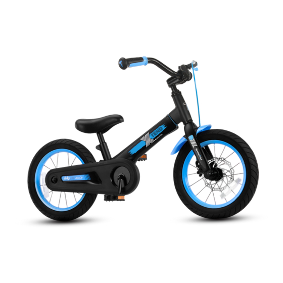
Ages 3-7yrs
Designed to fit riders with measurements
Inseam: 47-59cm , Height: 95-125cm
™
Max load 50kg
Teach them to ride
Balance
age 3 - 4yrs
Watch them go...
Pedal
age 4 - 6yrs
See them fly!
Bike
age 6 - 7yrs
-1-
Advertisement

Related Manuals for SmartTrike Xtend Mg+


Summary of Contents for SmartTrike Xtend Mg+
- Page 1 20701A www.smarTrike.com www.youtube.com/user/smartTrikeO cial Ages 3-7yrs Designed to fit riders with measurements Inseam: 47-59cm , Height: 95-125cm ™ Max load 50kg Teach them to ride Balance age 3 - 4yrs Watch them go... Pedal age 4 - 6yrs See them fly! Bike age 6 - 7yrs...
- Page 2 Assembly parts BEB1503 BEB1101 BEB1002 BEB1008104 BEB1024201 BEB1013201 BEB1004102 BEB1213101 BEB1011201 BEB1508101 BEB1509101 / BEB1020201 BEB1025201 BEB1026201 BEB1027201 17mm 15mm...
- Page 3 Owner’s Bicycle Identification Record Under the body tube NOTE: This information is available only on the bicycle. As shown in the image, our bicycle has the production date code stamped into its body (model / STB / month /year). 3 Steps to Adjust the Bike to the Rider Assemble the bike.
- Page 4 Warning and Safety Information Meanings of Warnings: This symbol is highly crucial. Carefully see the word “CAUTION” or “WARNING” which follows it. The word “CAUTION” is provided before mechanical instructions. In case you do not obey these instructions carefully, mechanical damage or failure of a part of the bicycle can take place. The word “WARNING”...
- Page 5 Rules of the Road WARNING: If the rider fails to obey the following “Rules of the Road”, he can su er from injury or others could be hurt. Obey all tra c rules, regulations, signs, and signals. You must wear a bicycle helmet that meets the local standard and the local safety standards.
- Page 7 Parts Assembly List Fitting the Description Description Frame Tyre (x2) Fork Tube (x2) Handlebar Rear Wheel Assembly Grips (x2) Front brake disc Handlebar Stem Hand Brake (x2) Seat Chain Seat Post Chain Cover Back Wheel Nut (x2) Clamp Head Set Bearings Balance Bike System Right Pedal Balance Bike System Bolts (x3)
- Page 8 Handlebar and Stem Installation WARNING: To prevent steering system damage and possible loss of control, the “MIN-IN” (minimum insertion) mark , on the stem must be below the top of the locknut B . NOTE: Remove plastic cap C from the end of the stem D .
- Page 9 Seat Installation Selon les normes européennes, ATTENTION: Afin d'empêcher n'insérez pas la selle au-delà de la que la selle ne soit trop lâche et marque supérieure (marque de prévenir une éventuelle perte d'illustration C ) de contrôle, la marque A "MIN-IN"...
- Page 10 Assembly Step 1: Turn the bicycle in upside down manner so the fork is upwards. Step 2: A. Remove the screw and keep it for the next step. B. Attach the fender as described and fasten with the screw. Step 3: Insert the wheel according to the arrow.
- Page 11 Step 4: A. Make sure the metal ring is positioned correctly according to the drawing. B. Lock and tighten the nuts on both sides of the wheel, use a 15 mm open wrench key. Step 5: Attach the footrest to the bottom of the frame using 5mm Allen key and 3 bolts.
- Page 12 Testing The Seat - Post Clamp Tightness To test the tightness of the seat-post clamp: Try turning the seat side-to-side. If the Seat Post moves in the seat tube: Tighten the Allen screw which is on the seat-post clamp. Repeat this test again, until the seat post does not move in the seat tube. Bell Feature Bell Feature: In case the mounting screw A is...
- Page 13 Testing Stem and Handlebar Tightness To test the tightness of the stem: Straddle the front wheel of the bike between your legs. Turn the handlebar in order to try and turn the front wheel. If the stem and handlebar turn without turning the front wheel, readjust the stem with the wheel and secure the stem bolt(s) tighter than before (about 1/2 revolution only at a time).
- Page 14 Balance bike mode to pedal mode Assembly parts Step 1: Turn the bicycle in an upside down manner so the front wheel is in the air. -No need to remove the wheels.- -14-...
- Page 15 Step 2: A. To loosen the 3 bolts use a 5mm Allen key. B. Remove the footrest and keep for future use. C. Separate the bolts and keep them aside for next stages. Step 3: Remove the plastic cover of the gear. Step 4: A.
- Page 16 Step 5: Tighten the screws so the pedal system can be locked to the body. Step 6: A. Remove the screw and keep it aside. Do not throw B-C. Cover the chain with the lid until you hear a “click” . -16-...
- Page 17 D. Replace the screw and secure it for locking purpose. Chain Adjustment WARNINGS: The chain must stay on the sprockets. In case it comes o the sprockets, It will not be possible to pedal. WARNINGS: NOTE: Ensure the rear wheel is in the Do not try to repair chain on your own.
- Page 18 Step 7: For screwing the pedals use the open wrench (15 mm). 17mm NOTE: Pay careful attention 15mm to the side pedals according to the presented mark on the pedal side. Step 8: Place the Seat Post red reflector carefully so that it points straight backward.
- Page 19 Europe -19-...
- Page 20 Extended Mode Step 1: A. First, you need mechanism to loosen the screw and nut. B. The telescopic must be pulled to the required measure. C. Tighten the screw and nut for locking the mechanism. -20-...
- Page 21 Step 2: A. To adjust the handlebar use the 6 mm Allen key. B. To lock the mechanism back use the Allen Key. -21-...
- Page 22 Europe -22-...
- Page 23 Repair and Service WARNING: The product must be frequently inspected. A failure to inspect the product and to make repairs or necessary adjustments can lead to injury to the rider or to others. Ensure that all the parts are properly assembled and adjusted as per the written instructions in this manual and any “Special Instructions”.
- Page 24 Inspection of the Bearings MAINTENANCE Regularly check the bearings of the bicycle. Make sure to lubricate the bearings annually or when they do not pass the below tests: HEAD TUBE BEARINGS The fork must turn smoothly and freely at all times. When the front wheel is o the ground, you should be unable to move the fork up, down, or side-to-side in the head tube.
- Page 25 Lubrication & Maintenance WARNING: Be careful not to over lubricate. In case oil gets on the wheel rims or the brake shoes, it will minimize the brake performance and thus a longer break distance will be necessary to stop the bicycle.
- Page 26 WARNING: ALWAYS WEAR YOUR HELMET WHEN RIDING THIS PRODUCT! Ensure that the helmet sits in a levelled manner on the head and low on the forehead. The strap sliders must be adjusted below your ear on both the sides. Make sure to buckle the chin strap and adjust the strap until it is securely fastened.
- Page 27 WARRANTY LIMITED WARRANTY: Even though your new bicycle is built in a tough manner, it is designed only for recreational use and not for commercial use or extreme riding. Subject to the highlighted limitations, this smarTrike bicycle is warranted to the original purchaser to be free from any kind of defects in materials and workmanship for a certain period from the date of purchase: 4 years for the frame and fork, 6 months for all Other bicycle component parts.
- Page 28 continued Even in such conditions bicycle riding can be naturally dangerous as bodily injury or death can take place, especially if the rider does not ensure that the safety and maintenance checks recommended in this manual are followed, if the rider does not wear a helmet, if he fails to follow the rules of the road, if he goes into tra c, rides double, or gets involved in aggressive stunts or extreme terrain riding.
- Page 29 -29-...
- Page 30 -30-...
- Page 31 www.smarTrike.com www.youtube.com/user/SmartTrikeO cial -31-...
- Page 32 20628140603 -32-...
Need help?
Do you have a question about the Xtend Mg+ and is the answer not in the manual?
Questions and answers