Table of Contents
Advertisement
Quick Links
Advertisement
Chapters
Table of Contents

Related Manuals for Meva MT 60


Summary of Contents for Meva MT 60
- Page 1 Shoring System MT 60 Technical Instruction Manual...
- Page 2 Shoring System MT 60 Product Features The MT 60 shoring system is a square load tower sized 1.70 m by Abbreviations, measurements, figures and tables 1.70 m and allows for safe work in great heights. Fall down acci- The abbreviation MT is used for the MT 60 shoring system. Any dents are avoided while work performance is increased.
-
Page 3: Table Of Contents
Contents This Technical Instruction Manual contains information, instructions Product overview ................. 4 and hints describing how to use the MEVA equipment on the con- Integrated safety features ..............6 struction site in a proper, quick and economic way. Most examples Planking .................... -
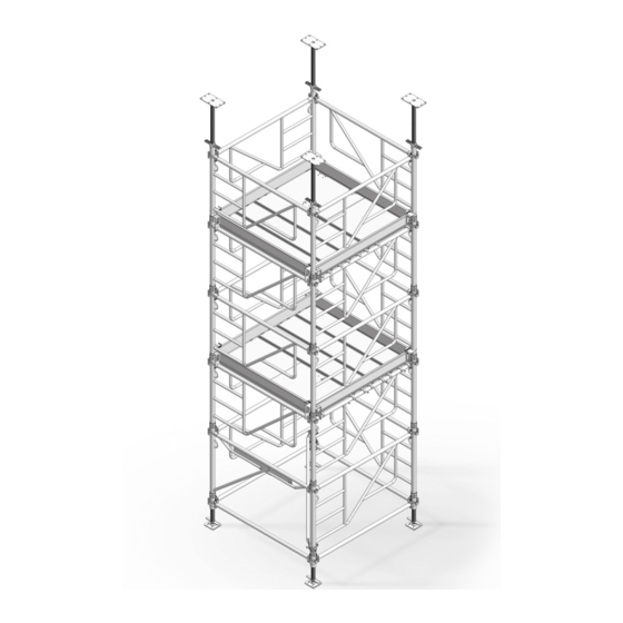
Page 4: Product Overview
MevaDec and MevaFlex. „ Each post has 60 kN load capacity. „ The entire tower can be wheeled from posi- tion to position if it does not have more than 5 levels. Access Fig. 4.1 Shoring system MT 60 MT4... - Page 5 Shoring System MT 60 Zeichnung Nr. 300506_0006-1 Product overview The tower is always assembled with the same standard parts no matter how high it is and what it is used for. Yet different accessories can be mounted to the head spindles to use the...
-
Page 6: Integrated Safety Features
Shoring System MT 60 Zeichnung Nr. 300506_0008_Detail_1 Integrated safety features Zeichnung Nr. 300506_0008 Zeichnung Nr. 300506_0008_Detail_4 The shoring system is equipped with a series of features and func- tions that maximize safety when assembling, using and transporting the tower. Detail 6.1.A... -
Page 7: Planking
Shoring System MT 60 Zeichnung Nr. 300506_0022 Scaffold platform Zeichnung Nr. 300506_0021 The scaffold platform is made of wooden planks inside an aluminium frame. The maximum load capacity is 200 kg/ m². Zeichnung Nr. 300506_0022-1 Bez.: Gerüstbelag 170 / 30 Bez.:... -
Page 8: Basic Tower 170 X 170 - Vertical Assembly
Shoring System MT 60 Basic tower 170 x 170 – Vertical assembly This page and the following ones show the vertical assembly of a standard tower with 3 levels. For a description Zeichnung Nr. 300506_0009-9 of the horizontal assem- bly see page MT-14. For... - Page 9 Zeichnung Nr. 300506_0009-8 Shoring System MT 60 Zeichnung Nr. 300506_0009-8.1 Basic tower 170 x 170 – Vertical assembly 8. Attach the frames 100 MT to the other spindles the way you attached the access frame in Step 7 (Fig. 9.1).
- Page 10 Zeichnung Nr. 300506_0009-6 Shoring System MT 60 Basic tower 170 x 170 – Vertical assembly 12. Suspend the scaffold platforms 170/30 for level 1 (Fig.10.1). 13. Ascend to level 1 and suspend the scaffold platform 170/68 with access hatch (Fig.10.2)
- Page 11 Zeichnung Nr. 300506_0009-4 Shoring System MT 60 Basic tower 170 x 170 – Vertical assembly Level 3 14. Standing on the scaffold platform of level 1, install the frames 100 MT for level 3 (Fig. 11.1) 15. Remove the scaffold...
- Page 12 Zeichnung Nr. 300506_0009-2 Shoring System MT 60 Basic tower 170 x 170 – Vertical assembly 17. Remove the from level 1 and install them on level 2 (Fig.12.1). 18. Climb up to level 2 using the ladder inte- grated in frame MT 100 (Fig.12.2).
- Page 13 Shoring System MT 60 Zeichnung Nr. 300506_0009 Zeichnung Nr. 300506_0009_Detail_2 Basic tower 170 x 170 – Vertical assembly 19. Plug the 4 head spin- dles MT into the frame posts and adjust them (Detail 13.1.A) 20. Toe boards are always installed at the highest working Zeichnung Nr.
-
Page 14: Basic Tower 170 X 170 - Horizontal Assembly Flat On The Ground
Shoring System MT 60 Zeichnung Nr. 300506_0037_2 Zeichnung Nr. 300506_0037_1 Basic tower 170 x 170 – Horizontal assembly flat on the ground The horizontal assembly Erecting the tower on the ground is done 1. Attach 4-rope crane with the same material... -
Page 15: Tower 170 X 340 - Vertical Assembly
Zeichnung Nr. 300506_0010-12 Shoring System MT 60 Zeichnung Nr. 300506_0010-11 Tower 170 x 340 – Vertical assembly Ground 9. Attach a horizontal Check that the ground is brace MT between two stable enough to sup- frames MT 100 to make port the tower. - Page 16 Shoring System MT 60 Zeichnung Nr. 300506_0010-9 Tower 170 x 340 – Vertical assembly 12. Suspend scaffold platforms 170/30 and scaffold platform 170/68 with access hatch for level 1 (Fig. 16.1). 13. Install ledger 170 Zeichnung Nr. 300506_0010-8 MT und diagonal brace 170/100 MT to brace both towers (Fig.
- Page 17 Shoring System MT 60 Zeichnung Nr. 300506_0010-6 Tower 170 x 340 – Vertical assembly Level 3 16. Standing on the scaffold platform of level 1, install the frames 100 MT for level 3 Zeichnung Nr. 300506_0010-5 (Fig. 17.1). 17. Remove the scaffold...
- Page 18 Shoring System MT 60 Zeichnung Nr. 300506_0010-3 Tower 170 x 340 – Vertical assembly 19. Remove the scaffold platforms from level 1 and install them on level 2 (Fig. 18.1). 20. Ascend to level 2 (Fig. 18.2). 21. Install toe boards...
-
Page 19: Working Platform Between Two Towers
Shoring System MT 60 Zeichnung Nr. 300506_0017_2D Working platform between two towers A safe working or walk- ing area between two towers can be achieved by installing either scaffold platform 170 or scaffold platform 220 and platform railing 170 or 220 respectively. -
Page 20: Transport By Crane
Shoring System MT 60 Zeichnung Nr. 300506_0020 Transport by crane The entire tower is transported in one lift. The 4-rope crane slings are attached to the crane eyes of the frames MT (Detail 20.1). Detail 20.1 Stand: 16.02.2016/bhe Fig. 20.1... -
Page 21: Transport On Wheels
Shoring System MT 60 Transport on wheels Zeichnung Nr. 300506_0011 Please note that trans- port wheels must only be used for towers with a maximum of 5 levels. By using transport Zeichnung Nr. 300506_0011 wheels the tower can be wheeled to another position as a complete unit. -
Page 22: Use With Slab Formwork Mevadec
MevaDec (Fig. 22.1) is assembled from the top platform of the tower. Note Make sure to follow the MevaDec Technical Instruction Manual when assembling, using and disassembling MevaDec. Fig. 22.1 Shoring towers MT 60 supporting the MevaDec slab formwork Stand: 30.03.2016/bhe MT22... -
Page 23: Use With Slab Formwork Mevaflex
MEP and attach it with two screws M12 and two lock nuts. Note Make sure to follow the MevaFlex Technical Instruction Manual when assembling, using and disassembling MevaFlex. Fig. 23.1 Shoring towers MT 60 supporting the MevaFlex slab formwork Stand: 30.03.2016/bhe MT23... -
Page 24: Disassembly
Shoring System MT 60 Zeichnung Nr. 300506_0051 Disassembly Important Before removing the slab formwork and disassembling the tower make sure and check that the poured con- crete has strengthened sufficiently. Disassembly procedure 1. Lower the slab form- work as follows: „... -
Page 25: Height Configurations From 2.51 To 6.42 M
Zeichnung Nr. 300506_0030 Zeichnung Nr. 300506_0028 Turmhöhe: 3,53 - 4,38 m Trumhöhe: 2,51-3,36 m Shoring System MT 60 Height configurations from 2.51 m to 6.42 m The required tower height is achieved by an adequate number of tower levels and by adjusting the spindles. -
Page 26: Height Configurations From 6.84 To 8.46 M
Shoring System MT 60 Zeichnung Nr. 300506_0034 Turmhöhe: 7,61 - 8,46 m Zeichnung Nr. 300506_0033 Height configurations from 6.84 to 8.46 m Turmhöhe: 6,84 - 7,70 m The required tower height is achieved by the number of tower levels and by adjusting the spindles. -
Page 27: Height Configurations From 9.65 To 12.54 M
Shoring System MT 60 Zeichnung Nr. 300506_0036 Height configurations from 9.65 to 12.54 m Turmhöhe: 11,69 - 12,54 m The required tower Zeichnung Nr. 300506_0035 height is achieved by the number of tower Turmhöhe: 9,65 - 10,50 m levels and by adjusting the spindles. -
Page 28: Material List - Tower Heights From 2.01 To10.76 M
Shoring System MT 60 Material list – Tower heights from 2.01 m to 10.76 m The table shows all mate- rial required to configure standard towers 170 by 170 cm for heights from 2.01 m to 10.76 m. Note The material required to... -
Page 29: Material List - Tower Heights From 10.16 To 18.66 M
Shoring System MT 60 Material list – Tower heights from 10.16 to 18.66 m The table shows all mate- rial required to configure standard towers 170 by 170 cm for heights from 10.16 m to 18.66 m. Note The material required to... -
Page 30: Transport And Storage
Shoring System MT 60 Zeichnung Nr. 300506_0050 Transport and storage Make sure that all mate- rial is secured properly. Recommendation Use one load/cargo strap per 1 metre of cargo. That means for a fully loaded truck with a trailer length of 13.60 m, 14 load or cargo straps would be required. -
Page 31: Important Work And Handling Rules
Shoring System MT 60 Important work and handling rules ¢ Any changes to the assembled scaffold only to be made by the con- tractor. ¢ When storing material on the deck, make sure to leave enough walking area on the deck. -
Page 32: Service
Shoring System MT 60 Service Cleaning RentalPlus Static calculations The formwork is cleaned Since MEVA started the Generally, this is only professionally upon flat rate for cleaning necessary for applica- return. Cleaning is done and repair of rented tions like singlesided...
Need help?
Do you have a question about the MT 60 and is the answer not in the manual?
Questions and answers