Table of Contents
Advertisement
Available languages
Available languages
Quick Links
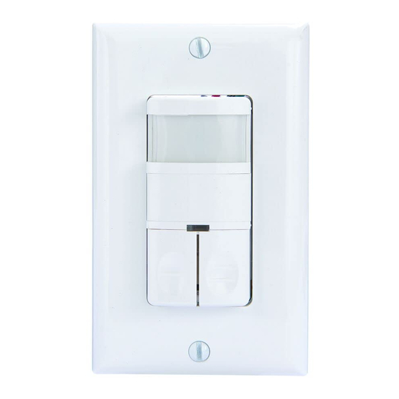
MODEL: IOS-DDR
Ratings:
Input Voltage: 120/277 VAC 50/60 Hz
Tungsten/ Incandescent: 800 W @ 120 VAC
Fluorescent/Ballast: 800 VA @ 120 VAC, 1600 VA @ 277 VAC
Electronic Ballast/LED: 800 VA @ 120 VAC, 1600 VA @ 277 VAC
Resistive: 800 W
Motor: 1/4 HP @ 120 VAC
Time Delay: 15 Sec to 30 Min
Light Level: 30 Lux--Daylight
Operation Temperature: 32˚F--131˚F / 0-55˚C
No minimum Load required.
INSTALLATION INSTRUCTIONS
Description:
The passive infrared sensors work by detecting the difference between heat emitted from the human body in motion and the background space.
The sensor switch can turn a load ON and hold it as long as the sensor detects occupancy. After no motion is detected for the set time delay, the
load turns OFF automatically. The IOS-DDR has two relays (equal to Dual Load Switch).
Coverage Area:
The coverage range of the sensor switch is specified and illustrated in Figure 1. Large objects and some transparent barriers like glass windows
will obstruct the sensor's view and prevent detection, causing the light to turn off even though someone is still in the detection area.
LOCATION/MOUNTING
Since this device responds to temperature changes, care should be taken when mounting the device. DO NOT mount directly above a heat source,
in a location where hot or cold drafts will blow directly on the sensor, or where unintended motion will be within sensor's field-of-view.
INSTALLATION
1. Connect lead wires as shown in WIRING DIAGRAM (see Figure 2): Black lead to Line 1 (Hot), Blue lead to
Line 2 (Hot), Red lead to Primary Load wire, Brown Lead to Secondary Load, Green lead to Ground.
2. Gently position wires in wall box, attach sensor switch to the box.
3. Mount device "TOP" up.
4. Restore power at circuit breaker or fuse, wait three minutes.
5. Remove the small cover plate. (Illustrated as Figure 3.)
6. Locate the adjustment knobs on the control panel to perform test and adjustments.
(Illustrated as Figure 4.)
7. Replace the small cover plate after testing and adjusting.
8. Attach the wallplate.
NOTE: If twist on wire connector is provided, use to join one supply conductor with one 16 AWG device control
lead.
ADJUSTMENT
Band Switch
Mode
Position
Description
OCCD
LEFT
Occupancy Mode: Dual Load Automatically ON,
Automatically OFF after set time delay both Loads
together
OCCS
Center
Primary Load
Occupancy Mode: Automatic ON, Automatic OFF
after set time delay.
Secondary Load
VCC Mode: Secondary Load Manual ON,
Automatic OFF after set time delay.
VACD
RIGHT
Vacancy Mode: Manual ON only.
Automatic OFF after set time delay
Time Delay Knob
Default position: 15 Seconds (Test mode)
Adjustable: from 15 Seconds to 30 Minutes (clockwise)
Sensor Sensitivity Range Knob
Default position: Center at 65%
Adjustable: 30% (Position 1) to 100% (Position 4)
Note: Turn clockwise for larger rooms. Turn counter clockwise to avoid false alerts in smaller rooms or near
doorway or heat source.
Back to factory default (daylight):
Set the Band Switch to VACD, press and hold the primary Manual ON/OFF Button for 6 seconds until the Load turns
on, continue holding the primary button for another 5 seconds until the Load turns off, then release the primary
button and set the Band Switch to OCCD or OCCS Mode, this confirms that the sensor switch goes back to factory
default.
OPERATION
The Sensor Switch is programmed independently for either Occupancy Mode or Vacancy Mode as referred to
the Band Switch position under the control panel cover. Vacancy mode is also known as "Manual ON Occupancy
Mode". There is a 5 seconds re-trigger delay between ON and OFF.
Turning On the load under Occupancy Mode
Load to be Automatic ON once occupancy is detected.
Turning On the load under Vacancy Mode
Manual ON/OFF Button has to be pushed to turn ON the Load.
Automatic Turning Off the load
Under all modes, the Sensor keeps the Load(s) On until no motion is detected for the set time delay, load(s) will
turn OFF automatically.
Manual Turn Off One Load
Another Load stays ON until no motion is detected and the set time delay. The manually turned OFF Load stays OFF
all the time.
IOS-DDR
WARNING
• Turn OFF power at circuit breaker or fuse and test that the power is OFF before wiring.
• To be installed and/or used in accordance with appropriate electrical codes and regulations.
• If you are not sure about any part of these instructions, consult a qualified electrician.
• Use this device only with copper or copper clad wire.
INDOOR USE ONLY
•
React to the pushbutton
Manually toggles On / Off
the loads.
Manually toggles On/Off the
loads.
Manually toggles On/Off the
loads.
Occupancy/Vacancy
(2-IN-1)
Sensor Switch
Dual Load
Risk of Fire, Electrical Shock or Personal Injury
Maximum: 1200 sq.ft.
Wiring Diagram
Dual Power Source
Neutral
Line 1 Black
Red
Red
Primary
Line 2 Blue
Load
Brown Secondary
Load
Ground Green
Neutral
10
20
2
Min
Min
30
1
TEST
Min
TIME
OCCD OCCS VACD
OCCD OCCS VACD
Top View
20'
10'
10'
20'
5'
180˚ Field of View
4'
40'
20'
Figure 1
Single Power Source
Neutral
Line Black
Red
Red
Primary
Blue
Load
Brown Secondary
Load
Ground Green
Figure 2
Figure 3
Mounting Yoke
Fresnel Lens
LED Indicator
Control Panel Cover
(Push Button)
3
4
RANGE
Primary Load Secondary Load
Figure 4
Advertisement
Table of Contents

Related Manuals for Intermatic IOS-DDR


Summary of Contents for Intermatic IOS-DDR
- Page 1 The sensor switch can turn a load ON and hold it as long as the sensor detects occupancy. After no motion is detected for the set time delay, the load turns OFF automatically. The IOS-DDR has two relays (equal to Dual Load Switch).
- Page 2 Después de que no se detecta movimiento durante el retardo establecido, Top View la carga se apaga automáticamente. IOS-DDR tiene dos relés (equivale a un Interruptor de Carga Doble). Máximo: 1200 pies cuadr.
- Page 3 Après un temps déterminé sans détection de mouvement, la charge est automatiquement désactivée. L’IOS-DDR comporte deux relais (équivalent à un interrupteur à double charge).
- Page 4 Ce service de garantie est disponible (a) en retournant le produit au vendeur auprès duquel l’unité a été achetée ou (b) en remplissant un formulaire en ligne de réclamation de garantie sur www.intermatic.com. Cette garantie est faite par : Intermatic...
Need help?
Do you have a question about the IOS-DDR and is the answer not in the manual?
Questions and answers