
Related Manuals for TILLQUIST LQT400


Summary of Contents for TILLQUIST LQT400
- Page 1 USER MANUAL LQT400 HUGO TILLQUIST AB Box 1120 SE-164 22 KISTA Sweden Tel: +46 8 594 632 00 info@tillquist.com www.tillquist.com Manual LQT400 Rev: EN2020-11-04...
-
Page 2: Thank You For Choosing Lqt400 From Hugo Tillquist Ab
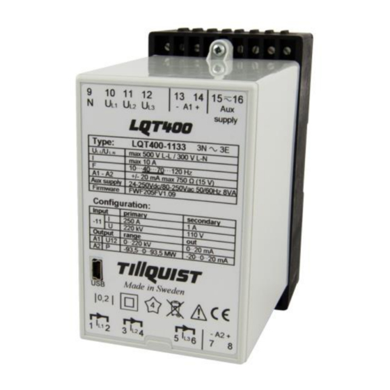
Thank you for choosing LQT400 from Hugo Tillquist AB! The LQT400 is a 3-phase multi-transducer with 2 analog outputs that can be configured to measure any electrical quantity. All areas for AC current and voltage (True RMS) are covered by one single unit. -
Page 3: Table Of Contents
Table of contents Thank you for choosing LQT400 from Hugo Tillquist AB! ......... i Product description ................... 1 Technical data ................... 1 Instructions......................2 Mounting ....................2 Installation ....................2 Operation ....................2 Warning! ....................2 Maintenance ..................... 2 Inputs - Outputs ..................3 Symbols on the appliance ................. -
Page 4: Product Description
1 Product description The LQT400 is a configurable 3-phase multi-transducer, capable for measuring any electrical quantity of a network. It is possible to choose up to 2 of any electrical quantities and link them to the analog outputs. The configuration is done using our freeware ConfigLQT via the mini USB-port. -
Page 5: Instructions
2 Instructions 2.1 Mounting The transducer is mounted on a 35mm DIN rail on a wall or device cabinet for suitable protection. The enclosure shall not be accessible without tools. 2.2 Installation The installation is to be made by competent personnel and in accordance with applicable regulations. -
Page 6: Inputs - Outputs
The installation kit consists of the configuration software and a driver for the USB connection to LQT400. ”.NET Framework” version 4.0 is a software from Microsoft, usually installed by default, that is necessary for the proper operation of ConfigLQT. If... -
Page 7: Configuration
3 Configuration 3.1 Connection to computer Connect a USB-cable between the USB-port on LQT400 and the computer. Use a cable with contacts type A and mini B. No safety action is required while connecting the USB cable to the device. -
Page 8: Monitored Parameters
Configuration using: choose which values will be shown. • Primary values – values based on primary data. • Secondary values – values based on secondary values. Read configuration: Read present settings from LQT400 to ConfigLQT. Apply configuration: Save data to LQT400. -
Page 9: System Connection
3.2.1 System connection Select the appropriate diagram for the used network. 3-phase 1 system 3-phase symmetrical load 1-phase 1 system 3-phase 1 system 3-phase symmetrical load 3-phase 1 system 3-phase symmetrical load 3-phase 1 system 3-phase symmetrical load 3-phase 1 system 3-phase symmetrical load 3-phase 2 systems... - Page 10 System connection Application I1 I2 I3 N U1 U2 U3 U12 U23 U31 4 wires 3-phase symmetrical load X - - X X - P1*3 Q1*3 S1*3 1 wire 1 phase X - - X X - 3 wires 3-phase symmetrical load X - - - - PI1U12 QI1U12 I1*U12*√3...
-
Page 11: Analog Outputs
3.3 Analog Outputs Click Analog Outputs tab to configure the analog outputs. Activation of an analog output. Drop-down list for selection of measured values and desired rows for the results . The analog outputs can be freely configured to the desired measured quantity within the allowed measuring ranges. -
Page 12: Measured Quantities
3.3.1 Measured quantities Prefix Quantity Calculation System / Phase Input current (I1+I2+I3)/3 System Phase current L1 Phase current L2 Phase current L3 Input voltage (U1+U2+U3)/3 System L1 Phase voltage L2 Phase voltage L3 Phase voltage Active power P1+P2+P3 System Active power L1 Active power L2 Active power L3 Reactive power... -
Page 13: Example Of Settings For The Analog Outputs
3.3.2 Example of settings for the analog outputs Measuring main voltage Secondary Analog out L1-L2 137,5 IN: 0 – 137,5 V OUT: 4 – 20 mA Secondary Analog out Measuring current I1 IN: 0 – 5 A OUT: 0 – 20 mA Primary Analog out -50000... -
Page 14: Save / Open Saved Configuration
3.4 Save / Open saved configuration The saved parameters of LQT400 can be saved to a file which can easily be downloaded to other transducers. 3.4.1 Save a configuration to a file 1. Select File menu and click Save as. . -
Page 15: Firmware Upgrade
4 Firmware upgrade The LQT400 firmware can be upgraded with the software ConfigLQT. To do so, connect the transducer to the computer with a USB cable. 1. Start ConfigLQT. 2. Select Firmware Upgrade from Transducer menu. 3. Choose the file with the new firmware and Upgrade.
Need help?
Do you have a question about the LQT400 and is the answer not in the manual?
Questions and answers