
Related Manuals for Kongsberg cJoy OT

Summary of Contents for Kongsberg cJoy OT
- Page 1 Kongsberg cJoy OT Joystick System Operator Manual Release 8.2 385585/C September 2015 © Kongsberg Maritime AS...
- Page 2 Kongsberg Maritime AS. Kongsberg Maritime AS endeavours to ensure that all information in this document is correct and fairly stated, but does not accept liability for any errors or omissions.
-
Page 3: Table Of Contents
System principles ....................11 The Kalman Filter..................12 The Controller ................... 13 Thruster allocation ..................14 USER INTERFACE ............15 cJoy OT operator terminal..................15 Controls and indicators...................16 Panel buttons and indicators ................ 16 Heading wheel and buttons................17 Dialog input buttons..................17 Input dialog selection buttons .............. - Page 4 Kongsberg cJoy OT General Setup ..................... 41 Sensors ...................... 42 Thruster Setup .................... 47 Alarm Limits ....................50 Pilot Setup....................52 Heading Setpoint pop-up dialog..............54 Changing and entering input dialog parameter values and options ....55 Closing input dialogs .................. 56 System status views and input dialogs ..............56...
- Page 5 Operator Manual Restarting the operator terminal ................81 Upgrading the operator terminal software..............82 Upgrading the controller PS software ..............82 OPERATING MODES ............85 Standby mode ......................85 Returning to Standby mode/manual levers ............ 86 Joystick mode ......................86 From Standby mode to Joystick mode ............87 Heading and position information ..............
- Page 6 Kongsberg cJoy OT Displayed VRS information............... 102 Enabling the VRS ..................102 Disabling the VRS ..................102 Faulty VRS ....................102 Speed sensors .......................102 Displayed Speed information..............103 Enabling a speed sensor ................103 Disabling a speed sensor ................103 Entering and enabling a manual speed value ..........
- Page 7 Operator Manual Setting the maximum rudder angle for joystick heading control ....120 Selecting the steering mode ............... 120 Selecting the steering group............... 121 385585/C...
-
Page 8: Glossary
Built-In Self Test BIST BITE Built-In Test Equipment Counter Clockwise Kongsberg Compact Joystick system cJoy cPos Kongsberg Compact Dynamic Positioning system Clockwise Dynamic Positioning Dynamic Positioning Controller Global Positioning System Input/Output International Maritime Organisation Kongsberg Maritime Kongsberg Dynamic Positioning system... -
Page 9: System Overview
System principles ......................11 The cJoy system The Kongsberg Joystick system (cJoy OT) is a computerised steering control system with manual, semi automatic and optional full automatic control capability. This system integrates control of the vessel's propulsion systems in a single joystick and has added features for automatic heading control and selection of vessel rotation point. - Page 10 Kongsberg cJoy OT The term “forces” in the following sections includes both forces and yawing moments, unless otherwise stated. The vessel's responses to these forces are measured by a gyrocompass, vertical reference sensor and position-reference system. Position-reference system readings are corrected for pitch and roll using readings from the vertical reference sensor.
-
Page 11: System Principles
This information is received from the vertical reference sensor. System principles A simplified block diagram of the cJoy OT system is shown in Figure 3, and described in the sections that follow. Figure 3 cJoy OT system block diagram... -
Page 12: The Kalman Filter
Kongsberg cJoy OT The Kalman Filter The Kalman Filter estimates the vessel's heading, position and velocity in each of the three degrees of freedom - surge, sway and yaw. It also incorporates algorithms for estimating the effect of sea current and waves. -
Page 13: The Controller
System overview • In the absence of position measurements, the model provides a “dead-reckoning” mode. This means that the system is able to perform positioning for some time without position updates from a position-reference system. In the Kalman Filter, the Mathematical Vessel Model's reliability and the noise level of the position measurement are the basis for deciding how much to trust each measurement. -
Page 14: Thruster Allocation
Kongsberg cJoy OT Thruster allocation The force demand in the surge and sway axes (the force setpoint), and in the yaw axis (the turning moment setpoint), is distributed to the various thrusters and propellers by the Thruster Allocation function. These setpoints are distributed in such a way as to obtain the force and turning moment... -
Page 15: User Interface
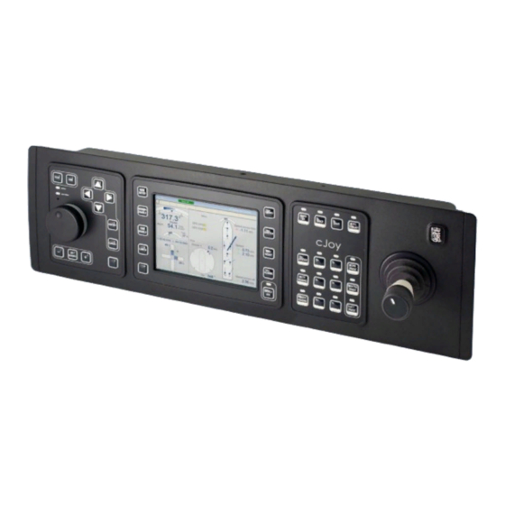
Input dialogs ........................40 System status views and input dialogs................56 cJoy OT operator terminal The cJoy OT operator terminal (cJoy OT) is the main operator interface for the stand-alone joystick system. It is designed for manual and semi-automatic joystick operations. Figure 5 cJoy OT operator terminal... -
Page 16: Controls And Indicators
Kongsberg cJoy OT On the grey standard version the button text or symbol is colour-coded to indicate the button type as follows: • White text or symbol on a dark background. Single-press action button for test, set-up, data input and operation monitoring. -
Page 17: Heading Wheel And Buttons
User interface Heading wheel and buttons This group comprises a heading wheel and three buttons. • The heading wheel increases and decreases the heading setpoint when the change heading function is active. • The button activates and terminates the change Set heading heading function. -
Page 18: Input Dialog Selection Buttons
Kongsberg cJoy OT Input dialog selection buttons This group comprises five buttons. General setup • The General setup button displays and closes the General Setup input dialog (see General Setup on page 41). Sensor button displays and closes the Sensor... -
Page 19: Silence/Ack. Button And Alarm Indicator
User interface Silence/ack. button and alarm indicator This group comprises a single button with an alarm indicator. • The button stops the audible signal horn from Silence/ack. Silence/ ack. sounding. It also acknowledges alarms and warning messages (see Acknowledging messages on page 66). •... -
Page 20: Joystick Buttons
Kongsberg cJoy OT • The Present heading button selects the present heading (see Stopping a change of heading on page 113). Note buttons can only be used if a Auto surge Auto sway position-reference system is installed. Joystick buttons This group comprises four buttons with green status indicators. -
Page 21: Display Layout
User interface Display layout The view shown on the display of the operator terminal is divided into areas: Title bar Message line Heading area View area Position area (CD3023) 385585/C... -
Page 22: Title Bar
Kongsberg cJoy OT The content of these areas, other than the working area, is fixed except for when the Equipment view or the Message view is being displayed (see Equipment view on page 57 and Presentation of messages on page 64). -
Page 23: Message Line
User interface In the example shown above, the Controller PS group is (the one to which Joystick: the operator terminal is connected) and the Command group is (which the system controls). Message line The message line shows the most recent Emergency, Alarm or Warning message that has not yet been acknowledged (see Presentation of messages on page 64). - Page 24 Kongsberg cJoy OT If no gyrocompasses are available, or the gyrocompass measurements are invalid, the vessel heading as estimated by the Vessel Model, based on the last known measured heading from the gyrocompass, is displayed. This is indicated by the background colour of the numeric value for the vessel heading changing to pink.
-
Page 25: Position Area
User interface Position area The Position area displays numerical and graphical information relevant for manual and automatic position control functions. This area is automatically arranged according to the current system state, and the location/orientation of the operator terminal on the vessel. If a position-reference system is installed (for the optional Station Keeping and Mixed Joystick/Auto modes) and it is enabled and providing valid position-reference data, the vessel... - Page 26 Kongsberg cJoy OT Mixed Joystick/Auto modes In the optional Mixed Joystick/Auto modes, the bar for the surge or sway axis under automatic control is replaced by a position deviation bargraph. The joystick setpoint and response for the axis in joystick control is indicated as described for the Joystick mode.
-
Page 27: View Area
User interface • Grey — Within the limits • Yellow — Warning limit exceeded • Red — Alarm limit exceeded Autopilot mode In the optional Autopilot mode, the joystick setpoint and joystick response for the surge axis is indicated as described for Joystick mode (see Joystick mode on page 25). -
Page 28: Main View
Kongsberg cJoy OT Main view The Main view shows information required during normal operation. The units shown on the view, i.e. metres/second ( ) or knots ( ) depend upon the type of units selected in the System Setup input dialog (see System Setup input dialog on page 58). - Page 29 User interface Graphical display of the vessel with thruster and main propulsion unit symbols in accordance with the vessel's thruster and propulsion configuration together with a thrust force symbol (in the centre) that shows the resulting thrust and turning forces. Each thruster and main propulsion unit symbol contains a blue vector that shows the thrust force and its direction relative to the surge and sway axes of the vessel.
- Page 30 Kongsberg cJoy OT If the rotation centre ( ) has been selected by the Fore RotCnt: button, the name of the rotation centre ( Pivot Aft Pivot Fore ) and its location relative to the centre of the vessel along the...
- Page 31 User interface If a sensor or position-reference system is disabled or not functioning correctly, the type of the sensor or position-reference system followed by a status indicator that changes colour is displayed. The colours shown by the status indicators of the sensors are: •...
- Page 32 Kongsberg cJoy OT Wind area area shows (by means of an arrow that points at a Wind vessel symbol) the direction of the wind relative to the fore/aft and port/starboard axes of the vessel. It also shows the true wind speed as numeric value.
- Page 33 User interface Orientation of the main view Each operator terminal automatically identifies its location and orientation (from information defined in the operator terminal junction boxes) in order to configure the joystick axis relative to the fore/aft and port/starboard axes of the vessel. The orientation of the Main view is configured according to the location and orientation of the operator terminal.
-
Page 34: Position-Reference System View
Kongsberg cJoy OT Position-reference System view The Position-reference System view is only provided if the optional Station Keeping mode is available. It shows the individual and resulting performance of the position-reference systems that are currently enabled. The values for the calibrated position (from the position-reference Position system) as used by the system. - Page 35 User interface The operational status of the position-reference system, Status which can be . If the Calibrating Online Offline Lost position-reference system is in a monitoring state (operating but not providing position-reference data) the status text is displayed with the prefix , e.g.
-
Page 36: Thruster View
Kongsberg cJoy OT Thruster view The Thruster view shows the overall status of all the vessels thrusters and main propulsion units (including rudders). Shows the running status of a thruster or main propulsion unit. Running The running status is often calculated. In this situation the running status is obtained from the ready status and normally they will be identical. -
Page 37: Thruster Subviews
User interface The azimuth angle setpoint of an azimuth thruster or rudder in Angle degrees. Indicates that the Thruster view is divided into one or more views. Indicates that the Thruster view has subviews for the thrusters and main propulsion units. Multiple Thruster views If the vessel has more than eight thrusters including the main propulsion units, the Thruster view will be divided into two or more views. -
Page 38: Sensor View
Kongsberg cJoy OT Sensor view The Sensor view shows the status and performance of each sensor. If the optional Autopilot mode is available the Sensor view will have at least two gyrocompasses and possibly one or more speed sensors. (sensor name) Shows if a sensor is enabled or not for use by the system. -
Page 39: Power Consumption View
User interface (Wind) The relative wind speed and direction as measured by the wind Speed sensor. (Wind) Direction (VRS) The vessel pitch and roll as measured by the vertical reference Pitch sensor. (VRS) Roll The following sign convention is used for pitch and roll: •... -
Page 40: Input Dialogs
Kongsberg cJoy OT The consumed power for each connect-switchboard is shown in graphical form as a percentage of available power for each connect-switchboard. The number of bargraphs shown will be automatically adjusted to reflect the vessel's current connect-switchboard configuration, i.e. when it changes due to bus-tie breakers being opened/closed. -
Page 41: Dialog Selection
User interface Dialog selection Input dialogs are selected and displayed in the View area by means of dedicated input dialog selection buttons (see relevant input dialog description). The only exception is the Heading Setpoint pop-up dialog which is displayed in the Position area of the display. -
Page 42: Sensors
Kongsberg cJoy OT Rate Of Turn Allows you to set the Rate Of Turn for change heading operations. Within the configured range the value can be increased and decreased in 5 degree steps (see Setting the Rate Of Turn on page 114). - Page 43 User interface If the optional Station Keeping mode is available the Sensor Enable input dialog will also show a position-reference system as shown in Figure 7. 385585/C...
- Page 44 Kongsberg cJoy OT Figure 7 Sensor Enable input dialog with a position-reference system If the optional Autopilot mode is available the Sensor Enable input dialog will include two gyrocompasses and one or more speed sensors. It will also comprise two dialogs;...
- Page 45 User interface Figure 8 Sensor Enable input dialog with two gyrocompasses Sensor The name and identification number of each position-reference system and sensor. Ready Shows if a position-reference system or sensor is available for use by the system. • Green — Available •...
- Page 46 Kongsberg cJoy OT Speed sensors The second dialog for speed sensors is used to enable and disable speed sensors, and enter a manual speed value that will be used to provide the system with speed information. To display this second dialog, press the button once more.
-
Page 47: Thruster Setup
User interface This field becomes unavailable and shows the current vessel speed if a speed sensor is enabled. Thruster Setup The Thruster Enable input dialogs are used to enable and disable the vessel's thrusters, main propulsion units and/or rudders for use by the system, and select the combinator control for thrusters and main propulsion units that can be controlled by both pitch and RPM. - Page 48 Kongsberg cJoy OT Running Shows the running status of a thruster or main propulsion unit. • Green — Running • Grey — Not running Ready Shows if a thruster, main propulsion unit or rudder is available for control by the system.
- Page 49 User interface MIN RPM Allows you to set the minimum RPM (in percent) for each of the listed thrusters. Within the configured range the value can be increased and decreased in 5 percent steps (see Setting the minimum RPM on page 96). This field is displayed as unavailable when is selected.
-
Page 50: Alarm Limits
Kongsberg cJoy OT Run in Select to turn on the Thruster Run-in function for the corresponding thruster. MAX setpoint (%) The maximum setpoint for the corresponding thruster in percent. The specified value must be more than any required minimum setpoint for the thruster (such as for minimum thrust or idle rpm) and must always be at least 20%. - Page 51 User interface If the optional Station Keeping mode is available, the Limits input dialog is also used to activate, de-activate and set warning and alarm limits for position deviation as shown in Figure 10. 385585/C...
-
Page 52: Pilot Setup
Kongsberg cJoy OT Figure 10 Limits input dialog with position warning and alarm limits Active Allows you to activate or de-activate ( ) a warning or alarm limit. Limit Allows you to set the value of a warning or alarm limit. - Page 53 User interface Figure 11 Pilot Setup input dialog Gain Level Allows you to select the gain level ( ) that is to be applied to the yaw axis for the autopilot control function (see Selecting the autopilot gain level on page 117). Counter Rudder Allows you to set the gain for the autopilot counter rudder function.
-
Page 54: Heading Setpoint Pop-Up Dialog
Kongsberg cJoy OT Rud. Lim. in Auto Yaw Control Allows you to set the maximum rudder angle when automatic heading control is active. Within the configured range the value can be increased and decreased in 1 degree steps (see Setting the maximum rudder angle for automatic heading control on page 119). -
Page 55: Changing And Entering Input Dialog Parameter Values And Options
User interface Turning the heading wheel to the right increases the value and turning it to the left decreases the value. Pressing the (increase) button steps the value up and pressing the (decrease) button steps the value down. The dialog is closed by pressing the button. -
Page 56: Closing Input Dialogs
Kongsberg cJoy OT Note Numeric values do not cycle. When the upper or lower end of the range is reached, the other arrow button must be used to increase or decrease the value. Saving changed values and options To save any changed parameter values and options, press the button. -
Page 57: Equipment View
User interface • System Information view Pressing the button when the System Information view is being displayed closes System the view. Equipment view The Equipment view shows the operational status for all configured stations and fills the display screen. Station The station name (i.e. -
Page 58: System Setup Input Dialog
Kongsberg cJoy OT • — Rebooting due to an error. Rebooting • — Stopped due to an error. Halt • — Operating normally. Operational • — A status has been reported, but communication is Not Communicational not possible. • — Not switched on. -
Page 59: Software Upgrade And Restart Input Dialog
User interface Units Allows you to select the type of units ( Modified Metric Metric Units Imperial ) that are to be used in views and input dialogs (see Display units on page 77). Units Note is basically the same as except that all speed values are Modified Metric Metric Units... - Page 60 Kongsberg cJoy OT Operator Terminal Shut Down this Operator Terminal Allows you to shut down the joystick application software and operating system running on the operator terminal so that power can be disconnected from the operator terminal (see Shutting down the operator terminal on page 80).
-
Page 61: System Information View
System Information view The System Information view shows the software configuration of the operator terminal. The displayed information can be useful for you to have available when contacting Kongsberg Maritime for help in case of problems with the system. 385585/C... -
Page 62: Message System
Kongsberg cJoy OT Message system This section contains the following topics: System diagnostics......................62 Operational checks......................62 Types of message ......................63 Presentation of messages ....................64 Acknowledging messages....................66 Alarm indicator ........................67 Operator pop-up messages....................68 Critical system messages ....................69 System diagnostics The following methods are used for fault detection: •... -
Page 63: Audible And Visual Indications
Message system • Comparison of received data with expected values calculated by the mathematical model. • Comparison of thruster setpoint and feedback signals. Discrepancies exceeding preset limits are handled as a fault. • Consistency checking between similar sensors. Detected faults and discrepancies are reported to the operator, enabling the appropriate operational actions to be taken and, if necessary, initiation of relevant repair procedures. -
Page 64: Presentation Of Messages
Kongsberg cJoy OT Information messages are only displayed in the Message view. For an explanation of these messages, refer to the message explanations in Appendix A at the end of this manual. If the system tests do not report the same message within a timeout period (usually 20 seconds), the message becomes inactive. - Page 65 Message system Figure 13 Message view (First column) Identifies the acknowledge status of the message: • An asterisk ( ) with its background colour flashing is displayed for an unacknowledged message that is in a command group over which the operator terminal has control.
-
Page 66: Acknowledging Messages
Kongsberg cJoy OT • — Message was reported by the controller PS and is now inactive (but not acknowledged). Time Time when the message was first reported ( hour:minute:second Pri. The priority of the message: • — Alarm • — Warning •... -
Page 67: Message View
Message system • If the message has been reported as inactive, it is removed from the Message line and replaced by the next most recent active Emergency, Alarm or Warning message. Message view To acknowledge the unacknowledged messages currently visible in the Message view, proceed as follows: Press the Alarms... -
Page 68: Operator Pop-Up Messages
Kongsberg cJoy OT A flashing alarm indicator shows that unacknowledged warnings and/or alarms are active. A steadily lit alarm indicator shows that all warnings and/or alarms have been acknowledged but are still active. The alarm indicator will extinguish three seconds after the last warning or alarm status has been removed. -
Page 69: Critical System Messages
Message system A typical example of each type of operator pop-up message: Critical system messages If certain system errors are detected, a critical system message is superimposed across the centre of the display. These messages are displayed when there is no response from the controller PS or for some reason an inconsistency in the system software parameters has been detected. -
Page 70: Software Inconsistency
DP Controller PS is now responding problem using the fault finding flowchart in the Maintenance Manual for your vessel. If this fails to find the cause of the problem, contact the Kongsberg Maritime Customer Support department for help. Software inconsistency... -
Page 71: Starting Operations
Starting operations Starting operations This section contains the following topics: System start-up ........................71 Panel test ..........................73 Panel dimming .........................74 Day and night palettes......................77 System date and time .......................77 Display units ........................77 Joystick calibration ......................77 System start-up The operator terminal and the joystick controller are usually left with power on and the system in Standby mode. -
Page 72: Taking Command
Kongsberg cJoy OT After the system has been started-up and its application software has loaded, the operator terminal and all connected wing terminals are automatically placed in Standby mode. Although all available information about the system is provided at each terminal, only one terminal can be in command of the system at any one time. -
Page 73: Panel Test
Starting operations • At all other terminals, the information ( ) or operator pop-up message INFO: is displayed, the audible signal horn sounds and the Take Receiving Command button status indicator starts to flash. At the terminal where command is to be taken, press the button twice within Take four seconds. -
Page 74: Panel Dimming
Kongsberg cJoy OT To terminate the panel test, press the Test button. • The panel test function is terminated. • The indicator changes to steadily lit green. operation Panel dimming The operator terminal stores two palettes for the display, one for day operation and the other for night operation. - Page 75 Starting operations Adjust the brightness level of the display as required. Press the button. Enter • The level indicator of the bargraph changes back to grey. Display Brightness • The bargraph is selected (green level indicator). Button Indicator Adjust the brightness level of the button status indicators as required. Press the Enter button.
- Page 76 Kongsberg cJoy OT Adjust the intensity level of the button background lighting as required. Press the button. Enter • The level indicator of the bargraph changes to grey. Button Backlight • The bargraph is selected (green level indicator). Volume Note...
-
Page 77: Day And Night Palettes
Starting operations Day and night palettes Two palettes are available, one for day use and one for night use that can be changed (toggled) by means of the button. Day/night Note The night palette is configured as default. To switch between day and night palettes, press the button. - Page 78 Kongsberg cJoy OT It may be necessary to calibrate the joystick when: • New system hardware has been installed or parts of the system hardware (for example the operator terminal) have been changed. • New system software has been installed or the system software has been re-installed.
- Page 79 Starting operations • The movement of the joystick in the X and Y directions is indicated by horizontal and vertical lines in each quadrant of the Joystick Calibration view. • The rotation of the joystick in the Z direction is indicated by a semicircle in the upper two quadrants of the Joystick Calibration view.
-
Page 80: System Procedures
Kongsberg cJoy OT System procedures This section contains the following topics: Shutting down the operator terminal................80 Restarting the operator terminal..................81 Upgrading the operator terminal software ...............82 Upgrading the controller PS software................82 Shutting down the operator terminal Prior to switching off the system you should always ensure that the operator terminal... -
Page 81: Restarting The Operator Terminal
System procedures Note To turn off the operator terminal, its 24 VDC power supply must be switched off in the joystick controller cabinet. For further details, refer to the Maintenance Manual for your vessel. Restarting the operator terminal If for some reason, you are required to shut down and restart the operator terminal, then it should be done in a controlled manner using the function Restart this Operator Terminal... -
Page 82: Upgrading The Operator Terminal Software
Software Upgrade and Restart input dialog is red, version match and then preferably by a Kongsberg Maritime software engineer. To upgrade the operator terminal application software from the flash PROM of the controller PS, proceed as follows: Display the Software Upgrade and Restart input dialog. - Page 83 Software Upgrade and Restart input dialog is red, version match and then preferably by a Kongsberg Maritime software engineer. To upgrade the application software stored in the flash PROM of the controller PS from the operator terminal, proceed as follows: Display the Software Upgrade and Restart input dialog.
- Page 84 Kongsberg cJoy OT • When the software upgrade has been completed, the field for the Status Upgrade function changes to green and all of the option fields Flash From this Terminal become available with the field in focus Upgrade Flash From this Terminal (selected).
-
Page 85: Operating Modes
Operating modes Operating modes This section contains the following topics: Standby mode ........................85 Joystick mode ........................86 Station Keeping mode......................91 Autopilot mode ........................92 Standby mode The Standby mode is a waiting and reset mode in which the system is in a state of readiness, but in which no vessel control commands can be made. -
Page 86: Returning To Standby Mode/Manual Levers
Kongsberg cJoy OT Returning to Standby mode/manual levers To return to Standby mode from any other mode: Press the button twice within four seconds. Standby • The button status indicator starts to flash and then becomes steadily Standby lit when the mode is entered. -
Page 87: From Standby Mode To Joystick Mode
Operating modes Figure 17 Operator terminal orientation Port Ahead Port Starboard Astern Ahead Astern Starboard Terminal orientation: Ahead Terminal orientation: Port Starboard Astern Ahead Starboard Port Astern Ahead Port Terminal orientation: Astern Terminal orientation: Starboard (CD3040A) Rotating the joystick turns the vessel (yaw axis). From Standby mode to Joystick mode When the system goes from Standby mode to Joystick mode, it will enable all ready and running thrusters. -
Page 88: Heading And Position Information
Kongsberg cJoy OT Heading and position information It is not essential to enable a gyrocompass and (if the optional Station Keeping mode is available) a position-reference system when operating in Joystick mode. However, the estimated position, heading and speed provided by the Vessel Model are meaningless if they have not been adjusted according to measured information. -
Page 89: Joystick Mode With Automatic Position Control In Both Surge And Sway
Operating modes • When the Rate Of Turn is reduced to less than a predefined limit, automatic heading control is enabled and the button Auto heading Present heading status indicators become steadily lit. The current vessel heading becomes the heading setpoint, and the system automatically maintains this heading. •... -
Page 90: Joystick Mode With Automatic Stabilisation
Kongsberg cJoy OT Returning to joystick position control To return to joystick position control, proceed as follows: Press the button twice within four seconds. Joystick • The button status indicators become unlit when Auto surge Auto sway automatic position control is disabled. -
Page 91: Station Keeping Mode
Operating modes • When the vessel speed (in the surge or sway axis) is reduced to less than a predefined limit, automatic position control in the selected axis is enabled and button status indicator becomes steadily lit. The Auto surge Auto sway current vessel position in the selected axis becomes the position setpoint in that axis and the system automatically keeps the vessel at this position. -
Page 92: Autopilot Mode
Kongsberg cJoy OT • The deviation between the estimated heading and the heading setpoint is shown in the Heading area of the display (see Automatic heading control on page 24). • When the vessel speed (in both the surge and sway axes) is reduced to less than... -
Page 93: Changing Heading
Operating modes Set the required Rate Of Turn (see Setting the autopilot Rate Of Turn on page 119). 10 Set the required maximum rudder angle for automatic heading control (see Setting the maximum rudder angle for automatic heading control on page 119). 11 Set the required maximum rudder angle for joystick heading control (see Setting the maximum rudder angle for joystick heading control on page 120). -
Page 94: Operating Procedures
Kongsberg cJoy OT Operating procedures This section contains the following topics: Thrusters ..........................94 Gyrocompasses ........................98 Wind sensor........................99 Vertical reference sensor ....................101 Speed sensors .........................102 Position-reference system ....................104 Selecting the vessel draught...................108 Joystick settings ......................109 Controlling the vessel heading..................112 Controlling the vessel position ..................114 Setting heading and position limits................115... -
Page 95: Enabling Thrusters
Operating procedures Enabling thrusters When a thruster can be enabled for joystick control, it is shown as Running Ready on the Thruster view (see Thruster view on page 36) and on the Thruster Enable input dialog (see Thruster Setup on page 47). There are generally two criteria for a thruster status: Ready... -
Page 96: Setting The Minimum Rpm
Kongsberg cJoy OT For the azimuth thrusters, you can choose between various thruster allocation modes. The currently-selected thruster allocation mode is shown in the field of Thruster Alloc the General Setup input dialog. Depending on the operational mode, illegal thruster allocation modes are unavailable in the General Setup input dialog. -
Page 97: Selecting The Combinator Mode
Operating procedures This minimum RPM is a limit which defines the lowest RPM that the thruster propeller will be allowed to rotate in either of these two modes. For example, if the minimum RPM is set to 60% then the range for the thruster propeller RPM will be set to 60 to 100%, i.e. the thruster propeller will not be allowed to rotate at less than 60% of its maximum RPM. -
Page 98: Gyrocompasses
Kongsberg cJoy OT Gyrocompasses At least one gyrocompass should be enabled at all times to provide heading information to the system for automatic control of heading. Rejection of heading measurements Normally, all available gyrocompasses will be running and enabled for use. -
Page 99: Disabling A Gyrocompass
Operating procedures Disabling a gyrocompass To disable a gyrocompass, proceed as follows: Display the Sensor Enable input dialog. Move the focus to the field for the gyrocompass and change the option to Enable If the optional Autopilot mode is available and if required, repeat step 2 for the other gyrocompass. -
Page 100: Displayed Wind Information
Kongsberg cJoy OT Normally, input from the wind sensor will be enabled. The system then receives and compares the signal from the sensor and uses it to calculate the wind force acting on the vessel. The raw measurements of wind speed and direction are filtered internally (using a Kalman filter with both low and high frequency parts), to estimate the most reasonable speed and direction values to be used by the system. -
Page 101: Operating Without Wind Sensor Input
Operating procedures To avoid this, the system performs the following test: • A wind speed measurement is rejected by the system if the wind speed is above a predefined limit (for example 15 m/s) and increases by more than a predefined value (for example 10 m/s). -
Page 102: Displayed Vrs Information
Kongsberg cJoy OT Displayed VRS information You can examine the status and measured values for the vertical reference sensor on the Sensor view (see Sensor view on page 38). Enabling the VRS To enable the VRS, proceed as follows: Display the Sensor Enable input dialog. -
Page 103: Displayed Speed Information
Operating procedures In high speed operations (e.g. in the optional Autopilot mode) all enabled speed sensors will normally be in use (unless a sensor has failed) when speed measurements are used by the system. It is recommended to also enable manual speed input since the manual value will be updated based on the in use sensors. -
Page 104: Disabling A Manual Speed Value
Kongsberg cJoy OT • If a high speed operation is selected the field changes to green. Manual SPD Close the Sensor Enable input dialog. Disabling a manual speed value To disable a manual speed value, proceed as follows: Display the Sensor Enable input dialog for speed sensors. - Page 105 Operating procedures • A prediction test detects sudden jumps or large systematic deviations in the measured position. The limit for the prediction test is a function of the estimated position in the Vessel Model and the actual measurement accuracy. If the results of the variance and prediction tests suggest that the position measurements from the reference system are not accurate, then the measurements are not used.
-
Page 106: Enabling The Position-Reference System
Kongsberg cJoy OT Reference high variance You should disable the position-reference system if the event of high variance is recurring. No corrective actions are necessary if the problem is intermittent only. Prediction test The prediction test detects sudden jumps in the measured position, and immediately rejects those that lie outside the limits as illustrated in Figure 18. -
Page 107: Disabling The Position-Reference System
Operating procedures To enable the position-reference system, proceed as follows: Display the Sensor Enable input dialog. Move the focus to the field for the position-reference system and change Enable the option to Press the button. Enter • An initial calibration of the position-reference system is performed. •... -
Page 108: Selecting The Vessel Draught
Kongsberg cJoy OT Position dropout This means that the system is currently using only the estimated position from the Vessel Model, and that this position has not been updated with measured positions for at least 20 seconds (“dead reckoning” mode). -
Page 109: Joystick Settings
Operating procedures Joystick settings Setting the joystick thrust There are two settings for joystick thrust: • Full The maximum force available from all thrusters can be used. This increases the vessel's response to movement of the joystick compared to the Reduced setting. •... -
Page 110: Environmental Compensation
Kongsberg cJoy OT • General Linear relationship between the movement of the joystick and force exerted by the thrusters. The is automatically changed from when Precision High Speed General changing from high-speed to low-speed manoeuvring (for example from Autopilot mode to Joystick mode). -
Page 111: Selecting The Vessel Rotation Centre
Operating procedures Disabling joystick wind compensation To disable joystick wind compensation, proceed as follows: Display the General Setup input dialog. Move the focus to the field and change the option to Wind Comp Press the button. Enter • Joystick wind compensation is disabled. Close the General Setup input dialog. -
Page 112: Controlling The Vessel Heading
Kongsberg cJoy OT Figure 20 Vessel For example, when manoeuvring alongside a quay which movement with Fore pivot lies to starboard, you may want to move the stern of the rotation centre selected vessel in towards the quay without the bow moving out, while at the same time applying a small thrust to starboard. -
Page 113: Stopping A Change Of Heading
Operating procedures Note The Heading Setpoint pop-up dialog must be displayed if rotation of the heading wheel is to have an effect. To change the heading setpoint, proceed as follows: Press the button once. Set heading • The heading wheel is activated. •... -
Page 114: Setting The Rate Of Turn
Kongsberg cJoy OT Setting the Rate Of Turn To specify the speed at which the vessel should turn during a heading change (i.e. the vessel's Rate Of Turn), proceed as follows: Display the General Setup input dialog. Move the focus to the field and change the value to the required speed. -
Page 115: Setting Heading And Position Limits
Operating procedures When the vessel is at the required position: Press the button twice within four seconds. The button Auto surge Auto surge status indicator starts to flash. • The vessel starts to slow down (loose speed) in the surge axis in a controlled manner at a rate that depends on the selected controller gain. -
Page 116: Position Deviation
Kongsberg cJoy OT When active, the heading limits are displayed as black lines — dashed for warning limit and solid for alarm limit, on the heading deviation shown in the Heading area of the display. When inactive, the heading limits are shown as gray lines. -
Page 117: Autopilot Setup
Operating procedures • The position deviation limits are changed to the selected values and activated. Close the Limits input dialog. Autopilot setup The optional Autopilot mode is set-up using the Pilot Setup input dialog. Selecting the autopilot gain level The gain applied to the yaw axis can be selected between three predefined levels, (50%), (100%) and (150%). -
Page 118: Setting The Auto Trim Gain
Kongsberg cJoy OT Figure 21 Effects of counter rudder settings New course Counter rudder setting too low overshoot response. New course Counter rudder setting too high, sluggish and creeping response. New course Correct setting of counter rudder ideal response. (CD3291) To change the counter rudder gain, proceed as follows: Display the Pilot Setup input dialog. -
Page 119: Enabling Weather Compensation
Operating procedures Press the Enter button. • The auto trim gain is changed to the selected value. Close the Pilot Setup input dialog. Enabling weather compensation Weather compensation (wind forces) can be enabled and disabled. When weather compensation is enabled, the vessel will react much more quickly to sudden changes in wind speed and direction. - Page 120 Kongsberg cJoy OT If you try to enter angle values beyond predefined limits, a message instructing you to correct the values will be displayed. To set the maximum rudder angle that can be used when automatic heading control is active, proceed as follows: Display the Pilot Setup input dialog.
- Page 121 Operating procedures The starboard steering unit generates the directional force. The port steering unit is fixed alongships. • (Asynchronous Port) Async PORT The port steering unit generates the directional force. The starboard steering unit is fixed alongships. To select the steering mode, proceed as follows: Display the Pilot Setup input dialog.
- Page 122 Message explanations APPENDIX A - MESSAGE EXPLANATIONS This Appendix contains (in alphabetical order) an explanation of the error messages that can be generated by the cJoy system. Table of contents Absolute reference system not active ................8 All reference systems rejected ..................8 Ascreate already done .....................
- Page 123 Message explanations Erroneous quality data ....................17 Erroneous telegram type ....................17 Error net A ........................18 Error net B ........................18 Estimator ROT limit exceeded ..................18 Estimator acceleration limit exceeded ................18 Estimator velocity limit exceeded ................19 Event limit exceeded ....................
- Page 124 Message explanations Insufficient thrust ......................29 Internal voltage test circuit error (see message) ............30 Invalid external connections ..................30 Invalid internal connections..................30 IO block linking failed ....................30 IO config error ......................31 IO error ......................... 31 IO input error ........................ 31 IO MAX no signal exceeded ..................
- Page 125 Message explanations PCU stopped by watchdog ................... 42 Position dropout ......................42 Position out of limits ....................43 Position presentation invalid ..................43 Position status error ...................... 44 Position status invalid ....................44 Power 24V failed ......................44 Power failure backupgyro ..................... 44 Power failure backup UPS ....................
- Page 126 Message explanations RIO: Function (opcode) is not in this revision/release ..........55 RIO: FW A version is less than minimum..............56 RIO: FW P is less than minimum................. 56 RIO: Ground monitoring error ..................56 RIO: Ground monitoring error, lower voltage limit exceeded........56 RIO: Ground monitoring error, upper voltage limit exceeded ........
- Page 127 Message explanations RIO: Selftest current error .................... 66 RIO: Self-test error (restart required) ................66 RIO: Selftest voltage error .................... 66 RIO: Short-circuit ......................67 RIO: Test channel error ....................67 RIO: Too low feedback while PDU=1 ................. 67 RIO: Too slow signal transition..................67 RIO: Voltage feedback outside tolerance ..............
- Page 128 Message explanations Telegram timeout ......................76 Thruster [#] input error pitch ..................76 Thruster [#] not ready ....................77 Thruster [#] prediction error ..................77 Thruster [#] ready running conflict ................77 Thruster [#] triangle pot error ..................77 Thruster in azimuth limits .................... 77 Thruster/rudder [#] input error ..................
-
Page 129: Absolute Reference System Not Active
Ascreate already done Description: This message shall not occur during normal operation, but is intended to be an aid for the software engineer during configuration/commissioning. Corrective Should the message occur during normal operation, contact Kongsberg Maritime actions: service. Astern thrust required Description: This message is reported if astern thrust is required when the Mean Offset function is in use. -
Page 130: Azimuth [#] Input Error Pitch
(given in parenthesis before the alarm-text), when returning the PS to Kongsberg Maritime Service. • Contact Kongsberg Maritime Service if this does not solve the problem. Azimuth [#] input error pitch See “Thruster/rudder [#] input error”. Azimuth [#] not ready See “Thruster/rudder [#] not ready”. -
Page 131: Block Status Is Not Available
Description: This message shall not occur during normal operation, but is intended to be an aid for the software engineer during configuration/commissioning. Corrective Should the message occur during normal operation, contact Kongsberg Maritime actions: service. Block type is not available... -
Page 132: Calibration Ok
Corrective • Check configuration. actions: • Should this message occur during normal operation, contact Kongsberg Maritime Service. Clock failure Description: This message is reported if the values read from the real time clock (in the PS (Process Station)) was outside accept-limits (for example, hour is negative or greater than 24). -
Page 133: Communication Port Reservation Error
If possible, try to change or swap PS (Process Station) with another. If the actions: error moves with the PS, it should be returned to Kongsberg Maritime Service for checking/repair (with indication of what processor is failing (given in parenthesis before the alarm-text)). -
Page 134: Demand Reduced Thruster [#] By Ext System
Message explanations Corrective Start more generators. actions Reorganize power distribution. Demand reduced thruster [#] by ext system Description: This message is reported if demand on this thruster is reduced by an external system. The method of detection is by digital input from external system read by the DP. Possible Position/heading drift-off and position/heading alarm may be reported. -
Page 135: Draught Limit Reached
Message explanations Draught limit reached Description: The used draught has reached the limits defined for maximum or minimum draught. The draught value will now be set to either high limit or low limit, depending on which of them has been violated. Additional •... -
Page 136: Draught [#] Sensor Rejected
Description: This message shall not occur during normal operation, but is intended to be an aid for the software engineer during configuration/commissioning. Corrective Should the message occur during normal operation, contact Kongsberg Maritime actions: service. Driver operation is not available... -
Page 137: Driver Task Creation Error
If possible, try to replace the PS (Process Station). actions: Note the alarm/message texts, describe the current operation executed and enclose this data when delivering the PS to Kongsberg Maritime Service for repair. Dual connection generator [#] Description This message is reported if at least two connections are found for a generator. -
Page 138: Enable Thrusters In Bow
PS to Kongsberg Maritime Service for repair. • Contact Kongsberg Maritime Service if this does not solve the problem. Enable thrusters in bow Description: This message will be reported if the system is in Auto Track High Speed mode and the use of bow thrusters is necessary for the vessel to enter the track at the required position/heading. -
Page 139: Error Net A
Message explanations Error net A Description: Most likely there is a disconnection somewhere in the failing network. The message rate exceeds 10 messages/100 seconds, but no message has been received on the failing network during this period. Possible The fault tolerance is reduced. As long as the other network is OK, there will be no consequences: operational consequences. -
Page 140: Estimator Velocity Limit Exceeded
• Check that the external clock is powered up. • Contact Kongsberg Maritime Service if this does not solve the problem. External Clock: Limit exceeded Description: This event is reported from a host which is master and synchronized from an external time source. -
Page 141: External Speed Receive Error
A Description: of what operations were executed in the time around when the PS stopped, must also follow the dump. • If something is not clear, contact Kongsberg Maritime Service. If the PS does not stop, inform Kongsberg Maritime Service about the incident. A-20 385585/C... -
Page 142: Fatal Internal Error In Memory/Ram/Flash Or Pci (See Message)
Try to replace the PS (Process Station). Note the alarm/message texts, describe the current operation executed and enclose this when delivering the PS to Kongsberg Maritime Service for repair. Contact Kongsberg Maritime Service if this does not solve the problem. Fix disabled Description This message is reported if the Fix allocation mode is disabled and the thruster allocation mode is changed to Variable. -
Page 143: Flash Uploading Failed
Downloading to Flash, uploading from Flash or booting from Flash may not work properly. Corrective Replace PS (Process Station) and return failing PS to Kongsberg Maritime Service. actions: (It is possible to try re-formatting the Flash device (Full Format), but replacing the PS is recommended.) -
Page 144: Fost: Illegal Channel Config
Message explanations FOST: Illegal channel config. Description: Passivate/FOST not executed. Illegal FOST channel configuration. Possible consequences: Corrective Replace card/check loop. actions: FOST: Passive side error Description: Passivate failed. DO NE: Drop in feedback voltage when trying to set to 0. Possible consequences: Corrective... -
Page 145: Fost: Shutdown Test Failed
Message explanations FOST: Shutdown test failed Description: FOST failed. No change in feedback within time. Possible consequences: Corrective Replace card/check loop. actions: Framing error Description: This message may be caused by errors in the position-reference system setup/DP setup. The data received does not match the configuration. No position from the position-reference system is received which may be caused by: Timeout. -
Page 146: Gps [#] Invalid
Message explanations Additional Load on the generator. information Possible An error on the load signal will not have any consequence as long as the generator consequences is disconnected. Two or more generators on affected swbd: The DP system will calculate with too low power available on the affected swbd if the generator is connected (failure in connect signal). -
Page 147: Gps [#] No Diff Data Received
Message explanations GPS [#] no diff data received Description The data received from the GPS indicated that there was not differential data. The GPS does not receive any data or have lost link to the diff stations. The reason for the fault may be that the differential data from diff station/radio link is lost or poor satellite configuration. -
Page 148: Gyro Not Enabled
Message explanations Gyro not enabled See “Sensor not enabled”. Heading dropout Description: This message is reported if no Gyro readings have been received for the past 2 seconds. The Gyro may not be ready, there may be an error in the connected Gyro or in the interface between the Gyro and the DP system. -
Page 149: Heading Prediction Error
Illegal buffer size Description: This message shall not occur during normal operation, but is intended to be an aid for the software engineer during configuration/commissioning. Corrective Should the message occur during normal operation, contact Kongsberg Maritime actions: service. Illegal channel specified Description: This message shall not occur during normal operation, but is intended to be an aid for the software engineer during configuration/commissioning. -
Page 150: Insufficient Memory In Dp Ps
Possible The DP-system may not function properly. consequences: Corrective Note the Additional information and contact Kongsberg Maritime Service. actions: Insufficient thrust Description: This message is reported when there is insufficient thrust. The reason for the fault may be that the number of enabled thrusters/propellers is inadequate. This can be detected by comparing thrust demand and obtained thrust. -
Page 151: Internal Voltage Test Circuit Error (See Message)
("Internal test circuit error xxx"). Try to replace the PS. Note the alarm text, describe the current operation executed and enclose this data when delivering the PS to Kongsberg Maritime Service. • Contact Kongsberg Maritime Service if this does not solve the problem. -
Page 152: Io Config Error
Corrective Correct the IO configuration file. actions: Should the message occur during normal operation, contact Kongsberg Maritime service. IO error Description: This message is reported if there is an error in the serial interface or in a telegram received from a position-reference system or sensor. -
Page 153: Io Max No Vote Signal Exceeded
Corrective Increase MAX_NO_SIGNALS in io_const.h or reduce the number of IO-signals in actions: the IO-configuration file. Should the message occur during normal operation, contact Kongsberg Maritime service. IO MAX no vote signal exceeded Description: This message is reported if the size of m1io exceeds GENERIC_MDATA_SIZE because of too many IO-signals configured for voting. -
Page 154: Manual Thrust Not Active
Message explanations Manual thrust not active Description This message is reported if the Manual Thrust mode is de-activated by system. The reason for this is that current system mode isn't matching the configured mode where this function can be used. The method of detection is on change in system mode. -
Page 155: Maximum Number Of Drivers Are Reached
This message shall not occur during normal operation, but is intended to be an aid for the software engineer during configuration/commissioning. Corrective Should the message occur during normal operation, contact Kongsberg Maritime actions: service. Message receive error or no read/write func. -
Page 156: Nb! Bad Terminal Io Connections Are Accepted
This message shall not occur during normal operation, but is intended to be an aid for the software engineer during configuration/commissioning. Possible System may not work properly. consequences: Corrective Should this message occur during normal operation, contact Kongsberg Maritime actions: Service. NB! Unconnected IO blocks are accepted Description: System is in test mode. -
Page 157: Net Invalid Message Received
Processor load. consequences: Corrective Identify the computer sending the message. actions: Check the configuration. Should the message occur during normal operation, contact Kongsberg Maritime service. Net storm detected on net A Description: Unexpected high message rate detected on net A. Possible... -
Page 158: Net Storm Protection Activated On Net B
• Net message number (tsap). • Status returned from operating system Possible None if it occurs just now and then. If it occurs continuously Contact Kongsberg consequences: Maritime Service. Net unknown address Description: This message is reported if a packet is received from an unknown address. -
Page 159: New Model Or Gain Updated From Ascii
Description: This message shall not occur during normal operation, but is intended to be an aid for the software engineer during configuration/commissioning. Corrective Should the message occur during normal operation, contact Kongsberg Maritime actions: service. No draught sensor accepted Description: None of the enabled druaght sensors are accpted by the system. -
Page 160: No Ready Rudder Or Steer Thruster
No idle force will be applied to the active thrusters. consequences: Corrective Change the software configuration. actions: Should the message occur during normal operation, contact Kongsberg Maritime service. No ready rudder or steer thruster Description: This message is reported if the number of ready thrusters, main propellers or rudders is insufficient. -
Page 161: On-Board Reference Voltage Error
• If OK, try to replace the PS. Note the alarm text, describe the current operation executed and enclose this data when delivering the PS Kongsberg Maritime Service. • Contact Kongsberg Maritime Service if this does not solve the problem. -
Page 162: Parity Error
Message explanations Corrective Enable another position-reference system. actions: Check the position-reference system and its setup. Check if the position-reference system is sending data. Parity error Description: This message may be caused by errors in the position-reference system setup/DP setup. The data received does not match the configuration. No position from the position-reference system is received which may be caused by: Timeout. -
Page 163: Parity/Overrun Error
Try to replace the PS (Process Station). • Note the alarm/message texts, describe the current operation executed and enclose this when delivering the PS to Kongsberg Maritime Service for repair. • Contact Kongsberg Maritime Service if this does not solve the problem. -
Page 164: Position Out Of Limits
Message explanations Possible The system uses the Vessel Model to estimate the vessel's position and velocities. consequences: If the external conditions change, the vessel may drift off position after a few minutes. When the "Position Dropout" message is reported, the setpoint is set automatically to the current estimated vessel position. -
Page 165: Position Status Error
Inspect and possibly replace fuse. • If power supply is failed, replace it. • Contact Kongsberg Maritime Service if this does not solve the problem. Power failure backupgyro Description: This is a digital input indicating that a backup gyro has power supply failure on one of its dual power sources. -
Page 166: Power Failure Backup Ups
Message explanations Power failure backup UPS Description: This message is reported if a power failure on the Backup system is detected. The reason for the fault may be UPS (Uninterruptible Power Supply) failure. The method of detection is a digital input on the Backup system. Possible Backup system unusable. -
Page 167: Power Out Of Range On Generator [#]
Message explanations Rescale the thruster pitch and/or generator power feedback signals. Power out of range on generator [#] Description: This message is reported if the measured generator power is negative or has a too great value. The reason for the fault may be the analogue input interface, a fault in the cabling or the feedback level has been changed such that the DP's internal scaling and bias factors are no longer correct. -
Page 168: Power Unbalanced Load On Thruster [#]
Message explanations Power unbalanced load on thruster [#] Description This message is reported if the percentage load on one or more of the diesels connected to the thruster differs considerably from the total load for the thruster, i.e. a unbalanced load is detected. The reason for the fault may be a fault in the analogue input interface, a fault in the cabling or the load percentage on the diesel is too high relative to the total load for the thruster. -
Page 169: Ps Degraded
Message explanations Allocation mode Wanted position Actual position Transponder coordinates PS Degraded Description: An error has occurred on the PS causing a possible reduced control capability. This may cause a redundancy master switch. Possible The Redundancy Group fault tolerance is reduced, but only related to the failing consequences: unit. -
Page 170: Rbus: Conflict Between Configured And Connected Rio Module Type
R/W : Error from RAM read/write/modify ADR: Error from RAM address line test. • Replace the PS (Process Station) and return to Kongsberg Maritime Service including the information described above. • Contact Kongsberg Maritime Service if this does not solve the problem. -
Page 171: Rbus: Rio Configuration Check Disabled
Message explanations Corrective Reduce size of configuration, split on more RCU's or change to RCU with more actions: memory. RBUS: RIO configuration check disabled Description: Given when either a redundant master is set in configuration mode, or a redundant slave is booted with initial redundancy update disabled. Possible The configuration CRC is discarded and the IO input will be read and accepted. -
Page 172: Reduced Thruster Alloc Capability
Message explanations Possible There is no immediate way to find a correct description of the error. consequences: Corrective Note message text and operational information. Contact customer support. actions: Reduced thruster alloc capability Description: This message is reported if the vessel cannot unconditionally provide thrust in all directions with the currently enabled thrusters. -
Page 173: Reference High Offset
Message explanations Reference high offset Description: This message is reported if a position reference system has an offset from the Vessel Model. The system is not rejected. The purpose of the test is to give an early indication of systematic errors before the position reference system is rejected by the prediction test. -
Page 174: Reference Median Rejected
Message explanations Additional • Limit for accepted median deviation. information: • Calculated median deviation. Possible The Vessel Model follows a faulty position reference system. consequences: Corrective Check if the median test detected the correct failure (one or more of the other actions: systems might have failed). -
Page 175: Reference Prediction Error
Message explanations Possible The reference system is no longer used. consequences: Corrective Deselect and check the reference system. actions: Reference prediction error Description: The difference between the position data from the reference system and the estimated position data from the Kalman filter exceeds the limit. The reference system is rejected. -
Page 176: Rio: Configuration Crc Error
Message explanations Corrective Note error data and operational information. Replace RIO module. Contact actions: customer support. RIO: Configuration CRC error Description: The RIO module has wrong configuration and must be reconfigured. Possible The RIO module is reconfigured by the active RCU master. consequences: Corrective Note message text and operational information. -
Page 177: Rio: Fw A Version Is Less Than Minimum
Message explanations Possible The FW version is too old to support expected functionality, and the RIO module consequences: will therefore not work properly. Corrective Download new RIO Firmware. actions: RIO: FW A version is less than minimum. Description: The RIO Module has a FW A version which is too old to communicate properly with the RBUS driver. -
Page 178: Rio: Ground Monitoring Error, Upper Voltage Limit Exceeded
Message explanations RIO: Ground monitoring error, upper voltage limit exceeded Description: The internal ground monitoring voltage reading for the non-isolated channels is above the application configured limit. Possible No immediate functional consequences, but if the condition persists, the signal consequences: values might be affected. -
Page 179: Rio: Ground Monitoring Error, (Iso2) Upper Voltage Limit Exceeded
Message explanations RIO: Ground monitoring error, (Iso2) upper voltage limit exceeded Description: The internal ground monitoring voltage reading for the isolated channel 8 is above the application configured limit. Possible No immediate functional consequences, but if the condition persists, the signal consequences: values might be affected. -
Page 180: Rio: Highside Driver Blocked On
Message explanations Possible Output signals are set to zero value. consequences: Corrective Check physical loop/cabling. Remove error, then activate manual reset. actions: RIO: HighSide driver blocked ON Description: Either a digital output value is stuck on “1”, or a digital input value had a too long value transition period. -
Page 181: Rio: Loop Mon. Error 4
Message explanations RIO: Loop mon. error 4 Description: Unknown loop monitoring error 4. Possible Is a symptom of an unknown FW error in the RIO module. consequences: Corrective Note error data and operational information. Contact customer support. actions: RIO: Loop mon. error 5 Description: Unknown loop monitoring error 5. -
Page 182: Rio: Not In Normal Io Mode. Automatically Set To Normal
Message explanations Corrective Note error data and operational information. Contact Customer Support. actions: RIO: Not in normal IO mode. Automatically set to normal Description: It is detected that the RIO module is in a test or calibration mode. The RBUS driver will automatically set the module to normal IO mode. -
Page 183: Rio: On-Board Voltage Error. Pwr2 (Reset Required)
Message explanations Possible All affected IO channels are marked with error, and if input, values are frozen to consequences: last valid value until the problem is solved and a manual reset is activated. Corrective Check cabinet power and earth connections. Try to reset the RIO Module. If this actions: does not help, replace the module. -
Page 184: Rio: On-Board Voltage Error. Ref2 (Reset Required)
Message explanations RIO: On-board voltage error. REF2 (reset required) Description: An internal reference voltage identified as REF2 is out of limits. Possible All affected IO channels are marked with error, and if input, values are frozen to consequences: last valid value until the problem is solved and a manual reset is activated. Corrective Check cabinet power and earth connections. -
Page 185: Rio: Pdu Turned Off (Reset Required)
Message explanations Possible To prevent damage to internal circuits, overload protection is activated. If signal is consequences: input, value is frozen to last valid input. If output, it is internally disconnected until the problem is solved and a manual reset is activated. Corrective Check physical loop/cabling. -
Page 186: Rio: Power B Failure (Restart Required)
Message explanations RIO: Power B failure (restart required) Description: The RIO module has detected power failure on RBUS B, and within an operational sequence that in this case will lead to lost communication. Possible The RIO module has probably stopped working altogether. consequences: Corrective Check RBUS B power/cabling. -
Page 187: Rio: Scheduler Stopped (Restart Required)
Message explanations consequences: Corrective Check physical loop/cabling. actions: RIO: Scheduler stopped (restart required) Description: The RIO module internal FW scheduler has stopped. Possible The RIO module is not functioning. consequences: Corrective Try to restart the RIO Module. If this does not help, replace the module. actions: RIO: Selftest current error Description:... -
Page 188: Rio: Short-Circuit
Message explanations RIO: Short-circuit Description: There is a short circuit between two field terminals or cables. Possible The device connected to the actual channel might not operate as intended. If consequences: signal is input, value is frozen to last valid input as long as alarm is active. Corrective Check physical loop/cabling. -
Page 189: Rudder [#] Input Error
The system might not function properly. consequences: Corrective • Check configuration. actions: • Should this message occur during normal operation, contact Kongsberg Maritime Service. SBC Fan stopped Description: The fan on the PS (Process Station) is not running. A-68 385585/C... -
Page 190: Sbc High Temperature
Ensure that the fan is properly connected or replace the fan. PS must be actions: replaced as a unit. • Contact Kongsberg Maritime Service if this does not solve the problem. SBC High temperature Description: The temperature in the Process Station is too high. -
Page 191: Sensor Difference
Message explanations Additional • Channel (e.g. for VRS; Roll Pitch or Heave) information: • For Gangway: sensor number. Not applicable for other sensors. Possible The DP system will automatically use data from the other enabled sensors. consequences: Corrective No actions are necessary if the error message is only reported occasionally. If actions: reported frequently, disable and repair the faulty sensor. -
Page 192: Seismic Ext Rot Speed Limit
Message explanations Seismic ext ROT speed limit Description The rate of turn limit received from the external seismic computer was less than operator selected rate of turn. Additional Rate of Turn received from external seismic computer (deg/min) information Operator selected rate of turn (deg/min) Possible Vessel might not be able to follow planned track/turn due to the limitation consequences... -
Page 193: Speed Gps [#] High Noise
The BOP (Blow Out Preventer)/Riser/Stack sensor status is not OK. The reading of sensor data failed internally in the DP, possibly due to a sensor interface error. Possible Sensor data cannot be used. consequences Corrective action Disable the sensor and contact Kongsberg Maritime Service A-72 385585/C... -
Page 194: Stack Overflow (See Message)
Possible The system parameters were not read properly. The system may become unstable consequences: and the PS (Process Station) may stop. Corrective Switch from DP to Manual control. Try to reset the PS. Contact Kongsberg actions: Maritime Service. 385585/C A-73... -
Page 195: System File Decode Ok
Additional Explanatory text information: Possible The system parameters are not read properly. The system may become unstable consequences: and the PS (Process Station) may stop. Corrective Try to reset the PS. Contact Kongsberg Maritime Service. actions: A-74 385585/C... -
Page 196: System File Write Error
Replace the PS (Process Station). actions: • Note the alarm text. • Describe the current operation executed. • Return the PS with the information enclosed, to Kongsberg Maritime Service. • Contact Kongsberg Maritime Service if this does not solve the problem. 385585/C A-75... -
Page 197: Telegram Checksum Error
PS to Kongsberg Maritime Service for repair. • Contact Kongsberg Maritime Service if this does not solve the problem. Telegram checksum error Description: This message is reported if there is a checksum error in a telegram received from a position-reference system/sensor. -
Page 198: Thruster [#] Not Ready
Message explanations Thruster [#] not ready See “Thruster/rudder [#] not ready”. Thruster [#] prediction error See “Thruster/rudder [#] prediction error”. Thruster [#] ready running conflict Description According to the read input signals the thruster is ready but not running. This is an inconsistent situation. -
Page 199: Thruster/Rudder [#] Not Ready
Message explanations Corrective If control seems to be degraded the thruster should be switched off. Check the actions: input/output interface. Compare measurements on the DP Operator Station display with indicators on the bridge console. Replace input interface if there is considerable deviation. -
Page 200: Thruster/Rudder [#] Triangle Pot Error
Message explanations Possible Thruster malfunction. consequences: Corrective Check the SVC (Kongsberg Vessel Control) Operator Station for details. actions: Thruster/rudder [#] triangle pot error Description: This message is reported because the input from the triangular "sine-cosine" pot. meter indicates an error. -
Page 201: Too Many Messages
If this is a vital task, the PS (Process Station) may not stop (go to failsafe) if e.g. an exception occurs in the task. Corrective Contact Kongsberg Maritime Service. actions: Transmission timeout Description: This message is reported if an expected telegram did not arrive within the timeout limit which indicates a fault in the net communication with the position-reference system/sensor. -
Page 202: Tunnel [#] Input Error Pitch
This message shall not occur during normal operation, but is intended to be an aid for the software engineer during configuration/commissioning. Possible System may not work properly. consequences: Corrective Should this message occur during normal operation, contact Kongsberg Maritime actions: Service. Unconnected IO modules Description: IO configuration error. -
Page 203: Ups Earth Failure
: "Unknown error. Testno=xx Address=xx ErrorData=xx". Note the alarm/message texts, describe the current operation executed and contact Kongsberg Maritime Service. UPS earth failure Description: This is a digital input indicating a UPS (Uninterruptible Power Supply) warning. It may be an earth failure detected by the UPS. -
Page 204: Vrs [#] Prediction Error
Message explanations VRS [#] prediction error Description This message is reported if the difference between the value read from the sensor and the historical data of the sensor exceeds a limit. The data from the erroneous sensor is not used by the system. The reason for the fault may be an error in the sensor or the interface to the sensor. -
Page 205: Watchdog: Timer/Interrupt Error
PS stopped, must also follow the dump. If something is not clear, contact Kongsberg Maritime Service. If the PS does not stop, inform Kongsberg Maritime Service about the incident. Watchdog: Timer/Interrupt error Description: The failure is probably a failure in the Watchdog timer, used for watching the task execution performance. -
Page 206: Wind Difference
If possible, try to change with another PS (Process Station). If the error moves with the PS (Process Station), the failing PS should be returned to Kongsberg Maritime Service. • Contact Kongsberg Maritime Service if this does not solve the problem. 385585/C A-85... - Page 207 Message explanations A-86 385585/C...
- Page 208 © 2015 Kongsberg Maritime...
Need help?
Do you have a question about the cJoy OT and is the answer not in the manual?
Questions and answers