
Subscribe to Our Youtube Channel
Related Manuals for ScienTECH Vector S200


Summary of Contents for ScienTECH Vector S200
- Page 1 (217) 352-9330 | Click HERE Find the Scientech D200PC at our website:...
- Page 2 Series Laser Power/Energy Meters Setup and Operating Procedures Indicator Model No._____________ Serial No._____________ P/N9467J 5205...
- Page 3 DETECTOR CALIBRATION DATA Calorimeter # 1: Model No: Serial No: Calibration Wavelength: Output Sensitivity (S): Time Constant (1/e): sec. Calibration Temp: °C Sub. Heater Resistance (R ohms Sub. Heater Voltage (V volts Sub. Heater Wattage (W watts Calorimeter # 2: Model No: Serial No: Calibration Wavelength:...
-
Page 4: Table Of Contents
Thank you for choosing a Scientech laser power and energy measurement system. The Scientech employees are pleased to provide you with instruments designed and manufactured for years of reliable service. Please read this manual completely before using the equipment. This information will enable you to fully utilize the instruments. -
Page 5: Astral Calorimeter Specifications
Astral Calorimeter Specifications: A C 2500 A C 25H D A C X 25H D A C 2501 A C X 2501 A C 25U V A C 2504 M odel Type A bs or ber Sur f ace Sur f ace Sur f ace V ol um e... -
Page 6: Vector Pyroelectric Detector Specifications
Vector Pyroelectric Detector Specifications M o d e l P H F 0 2 P H F 0 5 P H F 0 9 P 0 5 P 0 9 A c tiv e D ia m e te r 2 m m 5 m m 9 m m... - Page 7 ABSORPTION OF HD ABSORBER vs WAVELENGTH CAUTION: SPECULAR REFLECTION WAVELENGH [nm] NOTE: Please exercise caution when using HD detectors. They exhibit spectral reflection of between 7% and 33%, of the input power, back out of the aperture. Please refer to figure above to determine the reflectance for the wavelength you are measuring.
-
Page 8: Unpacking And Setup
Unpacking and Setup The indicator and the sensor and accessories are packed in corrugated supports. All packing material should be saved for future damage free shipments. Before making any connections, verify that the power (VAC) requirement shown on the power entry module is compatible with the actual AC power outlet to which the indicator will be connected. - Page 9 MODEL D200PC Any Scientech Vector pyroelectric sensor may be connected to channel A and any Scientech Astral calorimeter to channel B. The input switches on channel A should be configured per the previous instructions for the S200 and D200P set up. The interconnect cable for the calorimeter terminates with mini-DIN connectors.
-
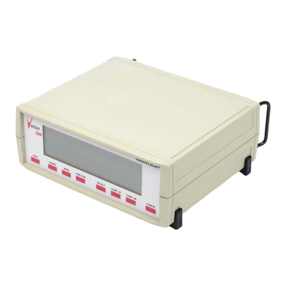
Page 10: Front Panel Controls
Operation FRONT PANEL CONTROLS RANGE Pressing the RANGE button begins a cycle through 6 ranges in the pyroelectric channel or 5 ranges in the calorimeter channel. In the pyroelectric channel if the 1 MΩ input impedance is selected the range cycle is 2 m, 20 m, 200 m, 2, 20, AUTO. -
Page 11: Select
Pressing the FUNCTION button begins the menu cycle of STATS, TUNE BAR, E, REMOTE (only if optional digital output is installed). Press the SELECT button when the desired function annunciator appears in the display. FUNCTION-Model D200P Pressing the FUNCTION button begins the menu cycle of CH AB RATIO, STATS TUNE BAR LOG E REMOTE, TRIG A TRIG B. -
Page 12: Save
SAVE Press the SAVE button to save the current setup to memory. This enables you to power cycle the indicator and return to the same indicator setup. The SAVE button must also be pressed after a calibration. OPERATING PROCEDURES Joulemeter sensor models P25, P50, SP25, SP50 P05,and P09 are coated with a special black absorbing material which provides a very flat spectral response over a broad wavelength band. -
Page 13: Set Electrical Time Constants For Model Phf02, Phf05 And Phf09
Remove the two slotted 4-40 binder head screws located on the underside of the detector. Pull off the outer housing to expose the battery. Remove the used battery from the battery holder and snap in the new battery. Slide the outer housing back in to place and secure with the screws. Figure 2 Do not touch the delicate pyroelectric crystals in the HR Series detectors. -
Page 14: Calibration
Calibration Calibration-MODELS S200, D200P Press the MODE button. When the CAL annunciator appears press the SELECT button. A menu of V/mJ, V/J, ATTEN will cycle. When calibrating for joulemeter sensor models P25, PHF25, SP25, SPHF25, P50, PHF50, SP50, and SPHF50, press the SELECT button when the V/J annunciator appears. Use the COUNT UP, COUNT DOWN buttons to enter into the display the V/J output sensitivity listed on the sensor ID tag. -
Page 15: Energy Mode
A portion of the beam would be measured by the transfer standard while the other portion is directed into the pyroelectric joulemeter. Select the average power mode by pressing the MODE button. Press the SELECT button when the mode annunciator appears. The menu will cycle through VOLTS, ENERGY, AVG ENERGY, and AVG POWER. Press the SELECT button when the avg power annunciator appears. -
Page 16: Power Mode
The AVG ENERGY mode in the D200PC only exists in channel A - the pyroelectric channel. Power Mode Average Power Mode - Models S200, D200P, D200PC (channel A) Select the appropriate range for the average power level to be measured. The average power mode displays the average power (watts) of repetitively pulsed lasers Minimum rep rate of 10 pps). -
Page 17: Statistics Mode
(CH A), channel B (CH B), the ratio of channel A to channel B (RATIO A/B), or the ratio of channel B to channel A (RATIO B/A). Trigger Channel Selection: Press the FUNCTION button to begin the menu cycle. Press the SELECT button when the TRIG A TRIG B annunciator appears. -
Page 18: Analog Output
Vpk is the peak voltage, TC is the time constant listed on the calorimeter serial tag, and Cal is the calorimeter output in V/W. The analog output is set at Scientech and should not be adjusted without consulting the factory. Joulemeter Sensor Operation With Oscilloscope The joulemeter sensors may be hooked-up directly with a 1 MΩ... -
Page 19: Calibration Using Electric Substitution Heating
Compare this resistance to R in the calibration data in front of the manual. The two should agree within 2%. If not contact Scientech. Remove the DVM. Connect a power supply to the SUB and HTR test points and connect the DVM to monitor the power supply. -
Page 20: Operation Of Astral Calorimeters With An Analog Chart Recorder
Figure 3 Operation of Astral Calorimeters with an Analog Chart Recorder Figure 4 Calorimeter Response The response of a calorimeter to a single pulse input as displayed by a chart recorder appears as in Figure 4. The output voltage from a chart recorder can be converted to wattage at any time by: W=V/S, W i =V i /S V=Chart recorder voltage level in mV S=Calorimeter sensitivity in mV/W... -
Page 21: Numerical Integration
1. Numerical Integration Finding the area under the curve in Figure 4 is the equivalent procedure for determining pulse energy. Choose an appropriate time interval, dt, and perform the summation: Σ Σ W i xdt=(dt/S) The error caused by this procedure is: Σ... -
Page 22: Calorimeter Damage Considerations
F=E/V p For the next pulse compute the total energy: E=F x V p The error in using this method yields: dE=FdV p + V p dF The accuracy of this measurement depends upon the error in the original calibration, dF, and the error in the peak voltage dV p . - Page 23 front to back. Because the absorber (glass) is a poor conductor of heat, the same laser power density will produce a much higher surface temperature than it would produce on the surface absorber. Furthermore, the glass will confine the heat laterally while the surface absorber does not. The maximum power density for the volume absorber is nearly one tenth that of the surface absorber.
- Page 24 Figure 7...
-
Page 25: Remote Interface
REMOTE INTERFACE REMOTE INTERFACE FOR MODEL AD30 AND PYROELECTRIC JOULEMETER INDICATOR MODELS S200 AND D200P, D200PC, D200C These units have two remote interface options: RS232, or IEEE488. Units with one or both of these options may be operated remotely via the interface selected. The remote interface language is compatible with the IEEE488.2 standard, and provides complete access to all instrument functions. - Page 26 If your instrument has both the RS232 and the IEEE488 interfaces installed, only one may be active at any given time. You can change the active interface from the front panel or from the remote interface itself. If the remote interface is the RS232 interface, and you wish to change it to the IEEE488 interface, you may enter the command "io ieee"...
- Page 27 As it comes from the factory, the configuration of the RS232 interface is 9600 baud, No Parity, No handshake. Should you desire to change this configuration, you can do it from either the front panel or the remote interface. Changing the setup from the front panel takes two steps: 1) Obtain the RS232 setup menu 2) Select the options desired Step 1) Obtaining the RS232 setup menu...
- Page 28 Setting the handshake method to XON causes the instrument to cease transmission upon receipt of an XOFF character (ASCII 19, CONTROL-S), and to resume transmission upon receipt of an XON character (ASCII 17, CONTROL-Q). Care should be taken when setting the handshake method from an RS232 communications device, to insure that the device then begins using the handshake method chosen.
- Page 29 e) The IO command is coupled to the *RCL and the *RST command, in that it puts a new value into the saved value for the active remote interface. This means that the use of the IO command may cause the RS232 remote interface to become the active interface the next time the unit is powered up, or the *RCL0 or *RST command is executed.
- Page 30 zero. To save the current instrument state, the user issues the *SAV 0 command. To restore the saved state, the user may issue either the *RST or the *RCL 0 commands). The *LRN? query is not supported. (20) The self test instigated by the *TST? query checks the ROM checksum against the contents of ROM, and it does a non-destructive RAM test.
- Page 31 *IDN? This query takes no arguments, and returns a comma separated collection of four strings, describing respectively the manufacturer of the instrument (Scientech Inc), the model number (D200,S200, or AD30), the serial number, and the firmware version number. *SAV 0 This is the IEEE488.2 common command.
- Page 32 switch settings (on pyros), or the type of sensor plugged into the amplifier (AD30). The meaning of the integer is described further in specifications of the individual instruments. RANGE <dec num> | auto Sets the range to the decimal number supplied, or makes range selection automatic.
- Page 33 *RST This is the ieee488.2 common command by the same name. When executed from the RS232 interface, it has the effect of restoring the saved instrument configuration. It has the additional function in the IEEE488 interface of forcing the interface into the OCIS state and the OQIS state. TUNE ON | OFF Turns the tune bar on or off.
- Page 34 ATTEN <dec num> Sets the attenuation factor to apply in the calculation of energy or power. In the D200 this command applies to the channel selected by the SEL command. D200P, D200PC, D200C SPECIFIC COMMANDS DSP A | B | A/B | B/A This command tells the dual channel indicator what to display on the front panel. An argument of A means display readings from channel A in the front panel.
- Page 36 IEEE488 SPECIFIC COMMANDS These commands may be used only from the IEEE488.2 interface. They are all members of the collection of so-called "common commands" described in the standard. *CLS Clears the Standard Event Status Register and forces the device into Operation Complete Command Idle state and Operation Complete Query Idle state.
- Page 37 Floating Point Display Mode (Normal vs Scientific): NORMAL Volts/Joule Channel A: 1.0 Volts/Joule Channel B: 1.0 Attenuation Factor Channel A: 1.0 Attenuation Factor Channel B: 1.0 Active Remote Interface: RS232 IEEE Bus Address (if installed): 4 S200 DEFAULT POWERUP SETTINGS The first time the S200 is powered up, the following settings have the values shown: RS232 Baud Rate: 9600 Baud RS232 Handshake Method: NONE...
- Page 38 Mode of Operation: POWER MODE Backlight Switch: OFF Tune Bar Display: OFF Floating Point Display Mode (Normal vs Scientific): NORMAL Time Constant: 8.0 seconds Active Remote Interface: RS232 IEEE Bus Address (if installed): 4...
-
Page 39: Model S200 Menu Trees
MODEL S200 MENU TREES FUNCTION BUTTON STATS TUNE BAR E(Scientific Notation) REMOTE RS232(OPTIONAL) IEEE488(OPTIONAL) BUS ADDRESS BAUD RATE PARITY HANDSHAKE EVEN NONE NONE 1200 2400 4800 9600 MODE BUTTON MODE VOLTS V/mJ ENERGY ATTEN AVG ENERGY AVG POWER (Transfer cal in avg power mode AVG POWER RANGE BUTTON 1MΩ... -
Page 40: Model D200P Menu Trees
MODEL D200P MENU TREES FUNCTION BUTTON STATS TUNE BAR LOG E REMOTE CH AB RATIO TRIG A TRIG B STATS TUNE BAR TRIG A CH A E(Scientific Notation) TRIG B CH B REMOTE RATIO A/B RATIO B/A RS232 IEEE488 BUS ADDRESS BAUD RATE PARITY HANDSHAKE... -
Page 41: Model D200Pc Menu Trees
MODEL D200PC MENU TREES FUNCTION BUTTON STATS TUNE BAR LOG E REMOTE CH AB RATIO STATS TUNE BAR CH A E(Scientific Notation) CH B REMOTE RATIO A/B RATIO B/A RS232 IEEE488 BUS ADDRESS BAUD RATE PARITY HANDSHAKE EVEN NONE NONE 1200 MODE BUTTON 2400... -
Page 42: Model D200C Menu Trees
MODEL D200C MENU TREES FUNCTION BUTTON STATS TUNE BAR LOG E REMOTE CH AB RATIO STATS TUNE BAR CH A E(Scientific Notation) CH B REMOTE RATIO A/B RATIO B/A RS232 IEEE488 BUS ADDRESS BAUD RATE PARITY HANDSHAKE EVEN NONE NONE 1200 2400 4800... -
Page 43: Limited Warranty
All Scientech Laser Power and Energy Measurement Systems are warranted against defects in materials and workmanship for two (2) years from date of delivery. During the warranty period, Scientech will repair, or at its option replace at no charge, components that prove to be defective. The equipment must be returned, shipping prepaid, to Scientech's product service facility.
Need help?
Do you have a question about the Vector S200 and is the answer not in the manual?
Questions and answers