Wavelength Electronics LDTC0520 Manual
Laser diode driver and temperature controller
Hide thumbs
Also See for LDTC0520:
- Datasheet and operating manual (27 pages) ,
- Datasheet and operating manual (27 pages)
Table of Contents
Advertisement
Quick Links
LDTC0520 / LDTC1020
Combine the low noise drive current of the FL500
with the temperature stability of the WTC3243
GENERAL DESCRIPTION:
The LDTC0520 combines a 500 mA, low noise
laser driver and 2.2 Amp temperature controller
on one small board. The LDTC1020 parallels
two 500 mA laser drivers to provide up to 1 Amp
of laser current with the 2.2 Amp temperature
controller.
The WTC3243 will control temperature using
thermistors, RTDs, or linear temperature sensors
such as the LM335 or the AD590.
temperature using the onboard trim pot or
a remote voltage input from a panel mount
potentiometer, DAC, or other voltage source.
A default temperature set point confi guration
provides fault tolerance and avoids accidental
damage to system components. Adjustable trim
pots confi gure heat and cool current limits.
The heart of the laser driver section is the FL500
500 mA Laser Driver. It maintains precision laser
diode current (Constant Current mode) or stable
photodiode current (Constant Power mode)
using electronics compatible with Common
Photodiode Cathode (Type A/B) lasers.
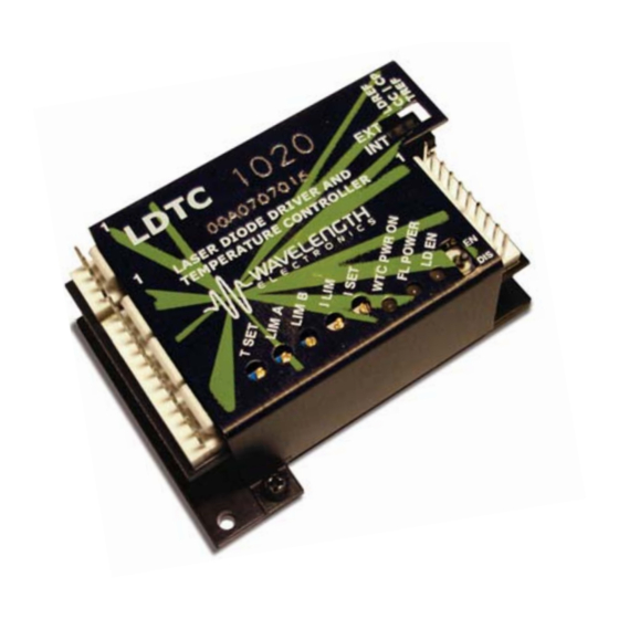
Figure 1
Top View Pin Layout
(Pin Descriptions on Page 7)
VDD_FL
VDD_WTC
LD SHD
EXT LD SET
ACT T M
SET T M
EXT T SET
© 2007
Adjust
TOP VIEW
(Actual Size)
J1
VS
GND
J2
SP1
SP2
COM
COM
LD P M
LD I M
COM
LDTC1020-00400-A Rev B
FEATURES:
• Small package size
• Single supply operation
• Cost Effective
• RoHS Compliant
FEATURES, Laser Diode Driver:
• Default current range is 500 mA or 1 Amp.
• Low Noise operation
• Slow start laser diode protection
• Constant Current or Constant Power modes
• Compatible with Common Photodiode
Cathode (A or B type) laser diodes
• Adjustable laser diode current limit
FEATURES, Temperature Controller:
• Drive up to 2.2A of TEC current
• Internal or External set point control
• Fail safe set point defaul
• Ultra-stable PI control loop
• Separate Heat & Cool current limits
• Single power supply operation
June, 2007
LDC
PDA
PDC
LDA
COM
TEC+
TEC-
SEN+
SEN-
COM
J3
www.teamwavelength.com
Advertisement
Table of Contents

Related Manuals for Wavelength Electronics LDTC0520


Summary of Contents for Wavelength Electronics LDTC0520
- Page 1 Combine the low noise drive current of the FL500 with the temperature stability of the WTC3243 GENERAL DESCRIPTION: FEATURES: The LDTC0520 combines a 500 mA, low noise • Small package size laser driver and 2.2 Amp temperature controller on one small board. The LDTC1020 parallels •...
- Page 2 PAGE 2 Figure 2 Schematic for FL500 connections © 2007 LDTC1020-00400-A Rev B www.teamwavelength.com...
- Page 3 PAGE 3 Figure 3 Schematic for WTC3243 connections © 2007 LDTC1020-00400-A Rev B www.teamwavelength.com...
-
Page 4: Absolute Maximum Ratings
Weight 3.13 LDTC1020 FL500 Laser Diode Driver Rating +3 to +12 Supply Voltage (Voltage on Pin 1) Volts DC Output Current (See SOA Chart), LDTC0520 (Single FL500) 1000 LDTC1020 (Dual FL500s) Power Dissipation, T = +25˚C, LDTC0520 (1) Watts AMBIENT... -
Page 5: Test Conditions
Constant Current, Sine Wave Bandwidth Constant Power (Depends on PD BW) Delayed Start msec Slow Start Ramp Rate mA/msec 100kHz sine wave Depth of Modulation LDTC0520 mA/V Transfer Function LDTC1020 mA/V POWER SUPPLY Voltage, V Volts Current, V supply, quiescent... - Page 6 PAGE 6 ELECTRICAL AND OPERATING SPECIFICATIONS, continued WTC3243, Temperature Controller PARAMETER TEST CONDITIONS UNITS TEMPERATURE CONTROL Short Term Stability, 1 hour TSET = 25˚C using 10 kΩ thermistor 0.005 ˚C 0.010 0.001 Long Term Stability, 24 hour TSET = 25˚C using 10 kΩ thermistor 0.008 ˚C 0.010...
-
Page 7: Pin Descriptions
PAGE 7 PIN DESCRIPTIONS Connector 1 (J1) Pin # Name Function Connect +3 to +12V between pins 1 & 4 to power the control Supply Voltage to Laser VDD_FL electronics and the output drive to the Laser Diode. Use the Driver Control Electronics online Safe Operating Area calculator to make sure maximum and Laser Diode... - Page 8 Refer to the chart shown below and note that the Load Line is in the Safe Operating Area. Note that this chart is for the LDTC0520 which contains a single 500 mA driver. The following page contains the performance graph for two parallel FL500 chips as used in the LDTC1020.
- Page 9 Refer to the chart shown below and note that the Load Line is in the Safe Operating Area. Note this chart is for the LDTC1020 which contains dual 500 mA drivers. The previous page contains the performance graph for a single FL chip as used in the LDTC0520 An online tool for calculating your load line is at http://www.teamwavelength.com/tools/calculator/soa/defaultld.htm.
- Page 10 PAGE 10 TYPICAL PERFORMANCE GRAPHS - WTC Caution: Do not exceed the Maximum Internal Power Dissipation of the FL or WTC. Safe Operating Area (SOA) tools are provided online to make your design easier. Exceeding the Maximum Internal Power Dissipation voids the warranty. To determine if specifi...
- Page 11 PAGE 11 WTC OPERATION CAUTION: Recommended order of setup: Operate the LDTC with loads attached - if you First complete the WTC temperature control short either the LD or TC output connections section THEN confi gure the laser diode driver. during setup, current will fl...
- Page 12 PAGE 12 WTC OPERATION, continued Confi guration of the LDTC for Alternate Temperature Sensors The standard LDTC confi guration is for Thermistor temperature sensors with 100uA bias current. The LDTC can be easily modifi ed to operate with other sensors and bias currents using the following instruc- tions.
- Page 13 PAGE 13 WTC OPERATION, continued Confi guration of the LDTC for Alternate Sensors, continued LM335 To use a National Semiconductor, LM335 temperature sensor with the LDTC, attach the LM335 cathode to Sensor+ and the LM335 anode to Sensor-. R , shown in BIAS Figure 4 should be changed to 2kΩ...
-
Page 14: Temperature Setpoint
PAGE 14 WTC OPERATION, continued 4. PROPORTIONAL GAIN AND 6. TEMPERATURE SETPOINT INTEGRATOR TIME CONSTANT - The temperature setpoint can be either remotely or locally controlled. An on-board trimpot (TSET) PI TERMS will adjust the voltage from 0.3V to 2.5V. The default settings of The LDTC are confi... - Page 15 PAGE 15 WTC OPERATION, continued 7. MONITOR ACTUAL TEMP AND SETPOINT Pins 9 and 10 of Connector 2 are the ACT T Monitor and SET T Monitor respectively. The ACT T monitor indicates the actual temperature sensor voltage and can be measured across Pin 9 and Pin 12 (COM).
-
Page 16: Select Mode Of Operation
PAGE 16 FL OPERATION 2. ATTACH THE FL POWER SUPPLY Recommended order of setup: Complete the WTC temperature control section THEN the FL laser diode driver. Use a The control electronics for the FL500(s) as simulated laser diode load until you are well as the laser diode current are supplied comfortable with the FL operation. - Page 17 The transfer function for the limit current voltage, measured at the limit set point is 250 mA / V Figure 9 for the LDTC0520. The transfer function for the Simulated Laser Diode Loads LDTC1020 is 500 mA / V. Constant Current Mode: 4.
-
Page 18: Current Monitor
The transfer function for calculating output current of 2mA for the LDTC. The 1kΩ resistor can be of the LDTC0520 is replaced by the user with a value more suitable to the sensitivity of the photodiode being used... - Page 19 The output current can be enabled and disabled using the on-board toggle switch. between the total input voltage and the laser diode current for the LDTC0520 is A remote voltage signal can be use to control the output status of the laser driver. Connect a zero = 250 mA / V volt signal to the “LD SHD”...
-
Page 20: Operation Notes
The LDTC does not support laser diode packages that incorporate a built in temperature sensor that is connected to or common with the laser case ground. ORDERING INFORMATION: LDTC0520 Comes with board, one FL500 Laser Driver, WTC3243 Temperature Controller, base plate, enclosure, and unterminated power, input and output... -
Page 21: Mechanical Specifications
PAGE 21 MECHANICAL SPECIFICATIONS © 2007 LDTC1020-00400-A Rev B www.teamwavelength.com... -
Page 22: Cable Diagrams
PAGE 22 CABLE DIAGRAMS POWER CABLE GREEN WHITE WCB-303 LDTC SERIES POWER CABLE BLACK WIRE COLOR 1 - VDD_FL GREEN 2 - VDD_WTC 3 - VS WHITE 4 - GND BLACK BLACK OUTPUT to WHITE BLUE TEC & LD GREEN RED W/ BLK WCB-301 LDTC2/2 SERIES... -
Page 23: Certification And Warranty
PAGE 23 CERTIFICATION AND WARRANTY CERTIFICATION: NOTICE: Wavelength Electronics (WEI) certifi es that this The information contained in this document is product met its published specifi cations at the subject to change without notice. Wavelength will time of shipment. Wavelength further certifi es...
Need help?
Do you have a question about the LDTC0520 and is the answer not in the manual?
Questions and answers