Table of Contents
Advertisement
Quick Links
DATASHEET AND OPERATING GUIDE
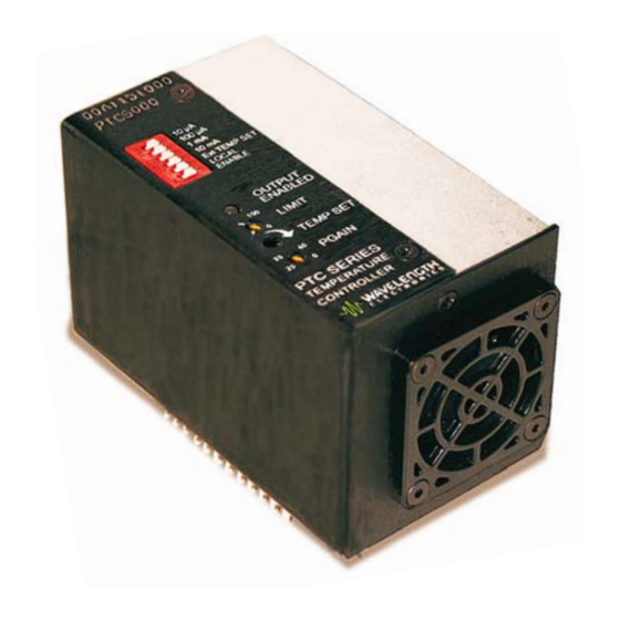
PTC5000/PTC10000
TIME-TESTED RELIABILITY
The PTC Series PCB-Mount Temperature Controllers are
based on our long-proven PTC-CH linear controllers, and
deliver the precision performance and reliability you expect
from Wavelength Electronics.
PTC Series controllers are found in such diverse
applications
as
particle
communications, manufacturing test, and medical systems.
CONTENTS
406-587-4910
www.teamWavelength.com
PCB-Mount Temperature Controllers
and
droplet
measurement,
Applies to PTC Product Revision A
Applies to PTCEVAL Revision A
FEATURES AND BENEFITS
• Drive ±5 or ±10 A of TEC or heater current
• Single supply operation: 5 to 30 VDC
• Small package: 2.32" x 2.15" x 3.85"
• Remote Output Enable and
Temperature Setpoint controls
• Short term stability of 0.0012°C (off-ambient)
• Long term stability 0.002°C
• Selectable sensor bias current
• Adjustable current limit
• PI Control with "Smart Integrator"
• Failsafe Setpoint default in case of remote
temperature setpoint signal error
POWERFUL AND EASY TO USE
The PTC controllers operate from a single power supply
between 5 V and 30 V, and two models drive ±5 A or ±10 A
to a Peltier thermoelectric cooler or a resistive heater.
These controllers mount directly to your circuit board.
PTC controllers interface with a variety of temperature
sensors, and the bias current is adjustable in order to
maximize controller sensitivity and stability for your
application.
You can use the PTCEVAL board to quickly confi gure the
PTC controller for prototyping. Using the same controller
for development and production helps guarantee there are
no surprises when it's time to integrate the fi nal design.
ORDERING INFORMATION
PAGE
2
PART NO
3
PTC5000
4
PTC10000
5
6
PTCEVAL
10
11
13
15
e
17
© November 2013
DESCRIPTION
±5 A Temperature Controller
±10 A Temperature Controller
Evaluation board for PTC-PCB
Series Controllers
Pb
RoHS
Advertisement
Table of Contents

Related Manuals for Wavelength Electronics PTC5000


Summary of Contents for Wavelength Electronics PTC5000
-
Page 1: Table Of Contents
5 V and 30 V, and two models drive ±5 A or ±10 A deliver the precision performance and reliability you expect to a Peltier thermoelectric cooler or a resistive heater. from Wavelength Electronics. These controllers mount directly to your circuit board. PTC Series controllers are found in such diverse... -
Page 2: Quick Connect Guide
IS IMPERATIVE THAT YOU DETERMINE THAT THE UNIT WILL BE on page 7. OPERATING WITHIN THE INTERNAL HEAT DISSIPATION (SOA). PERATING Go to the Wavelength Electronics website for the most accurate, up-to-date, and easy to use SOA calculator: http://www.teamwavelength.com/support/calculator/soa/soatc.php http://www.teamwavelength.com/support/calculator/soa/soatc.php 10 μA Sensor Bias Current Switches (Left = On) 100 μA... -
Page 3: Pin Descriptions
PTC5000 / PTC10000 / PTCEVAL PIN DESCRIPTIONS Table 1. Pin Descriptions NAME DESCRIPTION Temperature setpoint voltage monitor. Refer to the Electrical Specifi cations for the voltage range. SetT MON Impedance 1 kΩ. Actual temperature sensor voltage monitor. Range 0 to 6 V. When the temperature is stabilized at ActT MON the setpoint the ActT MON voltage will match the voltage at pin 1 (SetT MON). -
Page 4: Electrical Specifications
PTC5000 / PTC10000 / PTCEVAL ELECTRICAL SPECIFICATIONS PARAMETER SYMBOL PTC5000 PTC10000 UNIT NOTE ABSOLUTE MAXIMUM RATINGS Supply Voltage or V+ 5 to 30 Internal Power Dissipation derating begins at 25ºC Case Operating Temperature -40 to 85 ºC Case Storage Temperature -65 to 125 ºC... -
Page 5: Safety Information
The goal is to make the voltage across the sensor match the setpoint voltage, and then keep them equal in spite of changes Go to the Wavelength Electronics website for the most accurate, to ambient conditions and variations in thermal load. -
Page 6: Operating Instructions
PTC5000 / PTC10000 / PTCEVAL OPERATING INSTRUCTIONS PREVENT DAMAGE FROM ELECTROSTATIC DISCHARGE The PTC requires minimal external electronics. If you are using Before proceeding, it is critical that you take precautions to the module on the benchtop or for prototyping your control prevent electrostatic discharge (ESD) damage to the driver system, we recommend the PTCEVAL board. - Page 7 PTC5000 / PTC10000 / PTCEVAL PRECONFIGURATION CHOOSE EXTERNAL VS. ONBOARD SETPOINT The PTC includes a 12-turn trimpot for onboard temperature setpoint control, or you can use an external signal. ONBOARD ADJUSTMENTS AND CONTROLS • External Setpoint. Set the Ext TEMP SET switch on the top of the unit to the left (EXTERNAL).
- Page 8 PTC5000 / PTC10000 / PTCEVAL WIRE THE PTC TEMPERATURE CONTROLLER SetT Mon Refer to Table 5 to determine which confi guration applies to ActT Mon your application, and then reference the associated fi gure for COMMON wiring instructions. TTL-Compatible ENABLE...
- Page 9 PTC5000 / PTC10000 / PTCEVAL SetT Mon ActT Mon COMMON TTL-Compatible ENABLE Enable = HI (Optional Input) TEC- See Note ² COMMON Optional External Setpoint * Pin 1 is the pin farthest from the fan. Figure 8. TEC with Positive Temperature Coeffi cient Sensor (AD590, LM335 or RTD) ©...
-
Page 10: Operating With The Ptceval Board
PTC5000 / PTC10000 / PTCEVAL Place the PTC unit on the evaluation board. Hold the PTC in OPERATING WITH THE PTCEVAL place and turn the evaluation board over. Insert the two screws BOARD through the small holes in the printed circuit board and tighten. -
Page 11: Additional Technical Information
Calculate the voltage that corresponds to the required current limit. PRODUCT VARIATIONS The transfer function is 0.2 V / A for the PTC5000 and 0.1 V / A for the PTC10000. We design and manufacture our products in-house, and that... - Page 12 Follow these steps to use the SOA Chart to determine if the PTC will be operating safely. Refer to the example SOA chart in Figure 12. Actual SOA charts for the PTC5000 and PTC10000 are shown in Figure 13 and Figure 14.
-
Page 13: Troubleshooting
PTC5000 / PTC10000 / PTCEVAL TROUBLESHOOTING PROBLEM POTENTIAL CAUSES SOLUTIONS Output will not enable Improperly confi gured • If you are using the evaluation board, make sure that the REMOTE switch on the PTC REMOTE switch on the top of the PTC unit is set to the –OR–... - Page 14 PTC5000 / PTC10000 / PTCEVAL TROUBLESHOOTING, CONTINUED PROBLEM POTENTIAL CAUSES SOLUTIONS Temperature does not Insuffi cient current driven to Increase the current limit - but DO NOT exceed the reach the setpoint the TEC or Heater specifi cations of the TEC or heater.
-
Page 15: Mechanical Specifications
2.32 10.72 0.42 [3.96] [5.08] 0.156 0.200 [43.59] 23.88 54.66 1.716 0.940 2.15 92.74 3.65 Figure 15. PTC5000 / PTC10000 Dimensions 35.56 27.46 1.40 1.08 3.480 0.137 26.04 20.88 1.03 0.822 6-32 UNC-2B 2 PLS RECOMMENDED CLEARANCE HOLE DIA. [3.9] 0.145 TYP Figure 16. -
Page 16: Ptceval Eval Board Dimensions & Schematic
PTC5000 / PTC10000 / PTCEVAL PTCEVAL EVALUATION BOARD DIMENSIONS & SCHEMATIC 139.70 Dimensions are in [mm] and inches. 5.50 5.08 129.54 All dimensions have 5% tolerance. 0.20 5.10 101.60 4.00 91.44 3.60 5.08 43.20 55.88 0.20 1.70 2.20 60.60 2.39 0.35... -
Page 17: Certification And Warranty
CERTIFICATION As a general policy, Wavelength Electronics, Inc. does not Wavelength Electronics, Inc. (Wavelength) certifi es that this recommend the use of any of its products in life support product met its published specifi cations at the time of shipment.
Need help?
Do you have a question about the PTC5000 and is the answer not in the manual?
Questions and answers