Table of Contents
Advertisement
Quick Links
DATASHEET AND OPERATING GUIDE
LDTC0520/LDTC1020
Laser Diode & Temperature Controllers
PROVEN RELIABILITY
SAVES YOU TIME AND MONEY
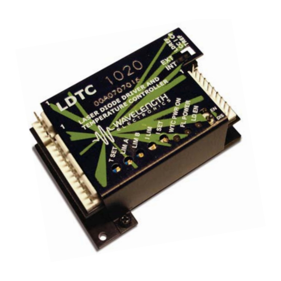
The LDTC Laser Diode and Temperature Controller
combines the proprietary FL500 and ultra-stable WTC3243
in one compact and easy-to-use module. All the controls and
indicators are onboard for simple plug-and-play operation.
APPLICATIONS
LDTC modules are in use around the world providing
trouble-free reliability in range finders, telecom laser
modules, military-aerospace research and development,
airborne metrology, academic research, laser diode LIV
testers, and more.
CONTENTS
406-587-4910
www.teamWavelength.com
FEATURES AND BENEFITS
• Small package size
• Single or dual supply operation
• LD current range 500 mA or 1 A
• Compatible with Type A and B lasers
• Slow start laser diode protection
• Constant Current or Constant Power modes
• Adjustable laser diode current limit
• Brownout protection
• Drive up to ±2.2 A of TEC current
• Internal or External setpoint control
• Failsafe setpoint default
• Ultra-stable PI control loop
• Separate heat & cool current limits
POWER YOUR APPLICATION WITH
THE RIGHT FEATURES
The popular FL500 is known for trouble-free operation.
The current limit circuit cleanly clamps laser diode current
without ringing or overshoot, and recovers without inducing
a phase shift in a modulated laser signal.
The WTC3243 ultra-stable temperature control module is
known for precision and reliability. Independent cooling-
and heating-current limits allow the LDTC to be used with
thermoelectric coolers or resistive heaters, and either
negative or positive temperature coefficient sensors.
ORDERING INFORMATION
PAGE
2
PART NO
4
LDTC0520
6
LDTC1020
MULTI-HTSK
8
HTSK-BRKT
9
13
15
22
23
25
26
Applies to Product Revisions A - C
© October 2018
DESCRIPTION
500 mA LD / ±2.2 A TEC Controller
1.0 A LD / ±2.2 A TEC Controller
Heatsink for LDTCxx20
Mounting bracket for MULTI-HTSK
e
Pb
RoHS
Advertisement
Table of Contents

Related Manuals for Wavelength Electronics LDTC0520


Summary of Contents for Wavelength Electronics LDTC0520
-
Page 1: Table Of Contents
DATASHEET AND OPERATING GUIDE LDTC0520/LDTC1020 Laser Diode & Temperature Controllers FEATURES AND BENEFITS • Small package size • Single or dual supply operation • LD current range 500 mA or 1 A • Compatible with Type A and B lasers •... -
Page 2: Quick Connect Guide
Temperature Controllers: www.teamwavelength.com/support/design-tools/soa-tc-calculator/ The model number is stamped on the top cover of the module. If the top cover is missing, the LDTC0520 has a single FL500 on the top; the LDTC1020 has two FL500 Laser Current Enable Status LEDs chips─one on each side of the circuit board. - Page 3 LDTC0520 / LDTC1020 LASER DIODE AND TEMPERATURE CONTROLLER RECOMMENDED TEST LOADS For initial setup and configuration, we recommend using a simulated load while configuring the laser diode driver, until familiar with the controller operation. To pre-test or troubleshoot, please use the following recommended test loads.
-
Page 4: Pin Descriptions
NAME PIN DESCRIPTION COLOR Connector J1, Cable WCB303 (included with LDTC0520 and LDTC1020) Laser driver and laser diode power supply input; 3 to 12 VDC. Current rated to at least 1.1‑times Green the laser diode forward current plus the driver quiescent current. Low-noise switching power supply DD_FL recommended. - Page 5 LDTC0520 / LDTC1020 LASER DIODE AND TEMPERATURE CONTROLLER Table 2. Control and Monitor Transfer Functions FUNCTION LDTC0520 LDTC1020 DESCRIPTION External setpoint input to control the laser drive current in Constant EXT LD SET, CC Mode 250 mA / V 500 mA / V Current mode.
-
Page 6: Electrical Specifications
LDTC0520 / LDTC1020 LASER DIODE AND TEMPERATURE CONTROLLER ELECTRICAL SPECIFICATIONS ABSOLUTE MAXIMUM RATINGS SYMBOL LDTC0520 LDTC1020 UNIT NOTE LD Supply Voltage 3 to 12 DD_FL TC Electronics Supply Voltage 4.5 to 12 DD_WTC TC Load Supply Voltage 4.5 to 30... - Page 7 LDTC0520 / LDTC1020 LASER DIODE AND TEMPERATURE CONTROLLER ELECTRICAL SPECIFICATIONS (CONTINUED) TEMPERATURE CONTROLLER UNIT NOTE SPECIFICATIONS OUTPUT CURRENT Max Output Current ±2.0 ±2.2 Compliance Voltage, TEC - 0.7 - 0.5 Full Temp Range, I = 100 mA Compliance Voltage, TEC...
-
Page 8: Safety Information & Thermal Design Considerations
CONSIDERATIONS WTC3243 in one compact module. SAFE OPERATING AREA — DO NOT EXCEED The LDTC0520 employs a single FL500 laser diode control chip; the LDTC1020 parallels two FL500 chips. The current INTERNAL POWER DISSIPATION LIMITS source continually monitors the actual output current,... -
Page 9: Operating Instructions Temperature Controller
LDTC0520 / LDTC1020 LASER DIODE AND TEMPERATURE CONTROLLER The controller measures the load temperature by driving a OPERATING INSTRUCTIONS current through the temperature sensor and measuring the TEMPERATURE CONTROLLER voltage drop across it. Similarly to the laser driver, you do not directly adjust the setpoint on the temperature controller;... - Page 10 LDTC0520 / LDTC1020 LASER DIODE AND TEMPERATURE CONTROLLER NECESSARY EQUIPMENT ONBOARD ADJUSTMENTS AND CONTROLS The following equipment is the minimum necessary to Figure 8 shows the onboard adjustments and controls that configure the LDTC for basic operation. are accessible with the cover on.
- Page 11 LDTC0520 / LDTC1020 LASER DIODE AND TEMPERATURE CONTROLLER WIRE THE TEMPERATURE CONTROLLER SET THE TEMPERATURE CONTROLLER POWER SUPPLIES AND TEST LOADS CURRENT LIMITS Reference Figure 9 to wire the temperature controller power These instructions are for a TEC application with an NTC supplies.
- Page 12 LDTC0520 / LDTC1020 LASER DIODE AND TEMPERATURE CONTROLLER WIRE THE LDTC FOR YOUR ADJUST THE TEMPERATURE SETPOINT TEMPERATURE CONTROL APPLICATION If the LDTC is configured for onboard temperature control, the setpoint is adjusted using the T SET trimpot, accessible Remove the test loads, and reconfigure the temperature through the hole in the cover.
-
Page 13: Laser Driver
LDTC0520 / LDTC1020 LASER DIODE AND TEMPERATURE CONTROLLER OPERATING INSTRUCTIONS SET THE LASER DRIVER CURRENT LIMIT Refer to the laser diode datasheet to determine the maximum LASER DRIVER allowable drive current (I ). Measure the exact resistance of the test load (R... - Page 14 LDTC0520 / LDTC1020 LASER DIODE AND TEMPERATURE CONTROLLER SET CONSTANT POWER OR CONSTANT EXTERNAL OR ONBOARD LD CURRENT CURRENT CONTROL MODE ENABLE Refer to Figure 12, and set the mode switch for Constant The laser output enable can be controlled from the onboard Current or Constant Power mode: the mode switch is the switch, or by an external signal.
-
Page 15: Additional Technical Information
LDTC0520 / LDTC1020 LASER DIODE AND TEMPERATURE CONTROLLER ADDITIONAL TECHNICAL SET THE CURRENT LIMIT WHEN USING RESISTIVE HEATERS INFORMATION The instructions on page 11 do not apply when a resistive This section includes useful technical information on these heater is used. Follow the instructions provided here instead. - Page 16 LDTC0520 / LDTC1020 LASER DIODE AND TEMPERATURE CONTROLLER WIRE THE LDTC TEMPERATURE CONTROLLER, ALTERNATE APPLICATIONS Spare The LDTC can be wired in a number of different configurations See Note AD590 using different temperature sensors and load transducers. TEC+ TEC- Table 4 identifies which wiring diagram to use for each case.
- Page 17 LDTC0520 / LDTC1020 LASER DIODE AND TEMPERATURE CONTROLLER SENSORS OTHER THAN A 10 kΩ THERMISTOR The LDTCxx20 is factory‑configured to bias a 10 kΩ thermistor with 100 µA current, but with simple modifications other sensors can be used. The instructions for making the...
- Page 18 LDTC0520 / LDTC1020 LASER DIODE AND TEMPERATURE CONTROLLER TEMPERATURE CONTROL LOOP TUNING The PI loop parameters are designed to work for a wide range of loads and applications. The factory defaults are: = R5 = 24.9 kΩ = 20 A / V] GAIN = R6 = 31.6 kΩ...
- Page 19 LDTC0520 / LDTC1020 LASER DIODE AND TEMPERATURE CONTROLLER ADJUST THE PHOTODIODE FEEDBACK EXTERNAL SETPOINT CIRCUITS CURRENT RANGE With the TREF and LDREF switches set to EXT (up) the LDTC will reference the analog inputs for the temperature The photodiode feedback resistor (R31) is 1 kΩ ±1%, and laser current setpoints, respectively.
- Page 20 LDTC0520 / LDTC1020 LASER DIODE AND TEMPERATURE CONTROLLER AN ALTERNATE METHOD FOR SETTING THE LASER DRIVER CURRENT LIMIT The laser drive current can be set while using the test load, as recommended on page 13, or it can be set while monitoring an internal test point.
- Page 21 LDTC0520 / LDTC1020 LASER DIODE AND TEMPERATURE CONTROLLER SAFELY TIE THE POWER SUPPLY INPUTS If the laser diode is case-grounded with either the laser anode or cathode tied to the case, then special attention must be paid to the power supply wiring.
- Page 22 LDTC0520 / LDTC1020 LASER DIODE AND TEMPERATURE CONTROLLER SAFE OPERATING AREA CALCULATION 0.50 To determine if the LDTC controller is suitable for your 0.45 application and if it will be operating in the safe range, 0.40 consult the instructions for calculating the Safe Operating 0.35...
-
Page 23: Troubleshooting Temperature Controller
LDTC0520 / LDTC1020 LASER DIODE AND TEMPERATURE CONTROLLER TROUBLESHOOTING TEMPERATURE CONTROLLER PROBLEM POTENTIAL CAUSES SOLUTIONS The convention is that the red wire on the TEC module connects to TEC+ (pin 6) Temperature is decreasing and the black wire to TEC‑ (pin 5). If your TEC is connected in this manner and when it should be increasing the problem persists, the TEC module itself may be wired in reverse. -
Page 24: Laser Driver
LDTC0520 / LDTC1020 LASER DIODE AND TEMPERATURE CONTROLLER TROUBLESHOOTING LASER DRIVER PROBLEM POTENTIAL CAUSES SOLUTIONS Driver will not switch on Improperly configured power supply Carefully check the wiring diagram on page 2. Make sure the power supply polarity is not reversed. - Page 25 LDTC0520 / LDTC1020 LASER DIODE AND TEMPERATURE CONTROLLER CABLING SPECIFICATIONS POWER CABLE – WCB303; INCLUDED WITH LDTCxx20 WIRE COLOR Molex KK 7880 Series Connector 1 ‑ VDD_FL GREEN Housing: Molex 10-11-2043 2 ‑ VDD_WTC Pin: Molex 46999-0101 3 ‑ VS WHITE 36”...
-
Page 26: Mechanical Specifications
LDTC0520 / LDTC1020 LASER DIODE AND TEMPERATURE CONTROLLER MECHANICAL SPECIFICATIONS DIMENSIONS – LDTC0520 / LDTC1020 2.10 [53.3] 2.60 2.90 [73.7] [66.0] 0.15 [3.8] 0.13 [3.3] 0.125 [3.18] 2.35 THROUGH, 2 PLS [59.7] 1.08 [27.4] 0.125 [3.18] Figure 36. LDTC0520 / LDTC1020 Dimensions All Tolerances ±5%;... -
Page 27: Certification And Warranty
CERTIFICATION AND WARRANTY There are no user-serviceable parts inside this product. Return the CERTIFICATION product to Wavelength Electronics for service and repair to ensure that safety features are maintained. Wavelength Electronics, Inc. (Wavelength) certifies that this product met its published specifications at the time of shipment.
Need help?
Do you have a question about the LDTC0520 and is the answer not in the manual?
Questions and answers