
Related Manuals for Wisenet PNM-9322VQP


Summary of Contents for Wisenet PNM-9322VQP
- Page 1 NETWORK CAMERA User Manual PNM-9322VQP SLA-2M2400P/2M2800P/2M3600P/2M6000P/ 2M1200P/5M3700P/5M4600P/5M7000P...
- Page 2 Network Camera User Manual Copyright ©2020 Co., Ltd. All rights reserved. Hanwha Techwin Trademark Each of trademarks herein is registered. The name of this product and other trademarks mentioned in this manual are the registered trademark of their respective company. Restriction Copyright of this document is reserved.
- Page 3 15. This product is intended to be supplied by a Listed Power Supply Unit marked “Class 2” or “LPS” and rated EXPLANATION OF GRAPHICAL SYMBOLS from PoE, 1.15A. (PNM-9322VQP) 16. This Lens module has to be connected with equipment, which supplied by a power supply unit marked “Class The lightning flash with arrowhead symbol, within an equilateral triangle, is 2”...
- Page 4 overview Class construction Please read the following recommended safety precautions carefully. An apparatus with CLASS construction shall be connected to a MAINS socket outlet with a ~ The product has a damp-proof component attached to it. Due to the nature of the product, dews may be formed after energizing the product, but they will disappear in two to three protective earthing connection.
-
Page 5: Table Of Contents
Recommended Micro SD/SDHC/SDXC Login Memory Card Specifications Camera Web Viewer Setup What’s Included (PNM-9322VQP) What’s Included (Lens module -optional) Optional Accessories for Installation At a Glance (PNM-9322VQP) At a Glance (Lens module) APPENDIX Troubleshooting INSTALLATION & CONNECTION Installation Connecting with other Device... -
Page 6: Recommended Pc Specifications
overview RECOMMENDED PC SPECIFICATIONS RECOMMENDED MICRO SD/SDHC/SDXC MEMORY CARD SPECIFICATIONS ~ CPU : Intel(R) Core(TM) i7 3.4 GHz or higher ~ RAM : 8G or higher ~ Recommended capacity : 16GB ~ 256GB(MLC type required) ~ Recommended browser: Chrome ~ Recommended Manufacturers : SanDisk, Transcend ~ Supported browsers: Chrome, Safari, Firefox, MS Edge(chromium based) ~ Product Type : High endurance ~ Supported OS : Windows, Mac, Linux, Android, iOS, Chrome... -
Page 7: What's Included (Pnm-9322Vqp)
WHAT’S INCLUDED (PNM-9322VQP) Appearance Item Name Quantity Description Please check if your camera and accessories are all included in the product package. (As for each sales country, accessories are not the same.) Waterproof accessories Used for installation in a humid area... -
Page 8: What's Included (Lens Module -Optional)
Item Name Description Model Name Model Name SBP-390WM2 SBP-300CMW SLA-2M2400P SLA-2M2800P Product type Corner mount Ceiling mount SLA-2M3600P Model Name SBP-300KMW SBP-300PMW SLA-2M6000P Lens module Mounted to PNM-9322VQP SLA-2M1200P Product type Parapet mount SLA-5M3700P Model Name SBP-300LMW SLA-5M4600P SLA-5M7000P 8_ overview... -
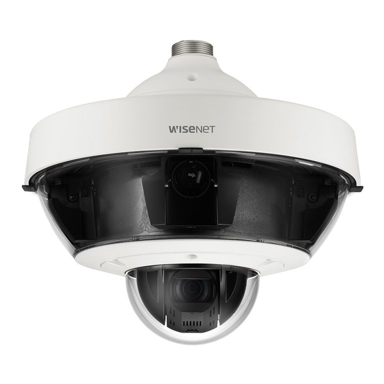
Page 9: At A Glance (Pnm-9322Vqp)
AT A GLANCE (PNM-9322VQP) Item Description Appearance Components Dome cover Case cover used to protect the lens and the main unit. Window cover Status Indicators for Lens If the lens module is attached correctly, the green LED will illuminate and then turn off after Module (normal: green, approximately 40 seconds. -
Page 10: At A Glance (Lens Module)
overview Installation side Inner View of Installation Base AT A GLANCE (LENS MODULE) Appearance Item Description Lens module This is a lens module that records video. Item Description Camera connector This is a terminal to connect with the camera. Alarm I/O Port Terminals that connect alarm I/O cables. -
Page 11: Installation & Connection
installation & connection INSTALLATION Inserting a Micro SD card 1. Using the Torx L wrench or screw bit(Torx 20), remove This camera is waterproof and in compliance with the IP66 spec, but the jack connected to the external cable is not. You are the dome cover and the micro SD card cover. - Page 12 installation & connection Removing a Micro SD card Mounting lens module 1. Gently press down on the exposed end of the Micro SD 1. Remove the cap from the lens module card as shown in the figure below to eject the Micro SD mounting portion.
- Page 13 If the product is installed in an area where outside moisture Preparing & Installing Camera Bracket can penetrate through the mount, use the provided cable For installation guidelines for brackets and housings, refer to the installation manual that is enclosed with the bushing to block the inflow of outside moisture.
- Page 14 installation & connection 3. Connect the network, I/O, and audio cable to the I/F 6. Turn the camera in the direction of the arrow so that the installation direction guides at the top and bottom PCB. are placed as shown below. For smooth joining with the PTZ camera, please be careful with the shape and form.
- Page 15 How to set up channels to monitor for installation Connecting the installation monitor The camera body has a channel DIP switch, as shown in the figure. Connect the Test Monitor Out Port of this product to the video input terminal of the monitor for installation. You can change the channel of the camera using the channel DIP switches.
-
Page 16: Connecting With Other Device
installation & connection Adjusting the monitoring direction for the camera CONNECTING WITH OTHER DEVICE Moving the camera module (Pan) Camera Wiring Interface Board For the camera wiring, please refer to the picture below. Alarm Alarm Input Audio input/ Tilt output Alarm output ` Adjusting the monitoring direction You can adjust the camera direction only when the camera is fixed on the ceiling. - Page 17 Connecting to Audio Input/Output Powering and networking Connect the HPoE injector with the HPoE port of the camera. Inner View of Installation Base Speaker SFP HPoE injector External internet Microphone SFP Port Switch Switch Network SFP module Speaker The product cannot be used at -35°C or below ambient temperature. Microphone The product may not be defrosted depending on the installation area at -35°C.
- Page 18 installation & connection SFP port Specification Support SFP Voltage 3.3 V Typical Support SFP Current 300 mA Max. Support SFP Cage Standard mini-SFP Cage(for 6.5 mm pitch SFP) Support SFP Port Type LC Type Required SFP Speed 1250 Mbps(For 1000 Mbps Ethernet) Required SFP’s BER(Bit Error Rate) Max 10 Transmission Method(Optical)
-
Page 19: Network Connection And Setup
network connection and setup CONNECTING THE CAMERA DIRECTLY TO A DHCP BASED DSL/CABLE You can set up the network settings according to your network configurations. MODEM CONNECTING THE CAMERA DIRECTLY TO LOCAL AREA NETWORKING Connecting to the camera from a local PC in the LAN INTERNET 1. -
Page 20: Using Device Manager
network connection and setup USING DEVICE MANAGER If using a Broadband Router ~ IP Address : Enter an address falling in the IP range provided by the Broadband Router. Device manager program can be downloaded from <Technical Guides>-<Online Tool> menu at Hanwha Techwin website ex) 192.168.1.2~254, 192.168.0.2~254, (http://www.hanwha-security.com). -
Page 21: Manually Registering Camera
~ Example of the Dynamic IP environment configure the IP. PNM-9322VQP - If a Broadband Router, with cameras connected, is assigned an IP address by the DHCP server 2. Click < + > at the main page of device manager. -
Page 22: Port Range Forward (Port Mapping) Setup
Port forwarding can be done without additional router setup if the router supports the UPnP (Universal Plug and Play) function. For more information, refer to the user manual of the applicable router. After connecting the network camera, select the checkbox from the menu <Quick connect> in <Wisenet DDNS> in “Settings -> Network -> DDNS”. -
Page 23: Connecting To The Camera From A Shared Local Pc
2. From the remote PC, launch the Internet browser and type the DDNS URL address of the camera, or the IP address of the Broadband Router in the address bar. ex) http://ddns.hanwha-security.com/ID To use Wisenet DDNS, sign up at the Wisenet DDNS homepage (http://ddns.hanwha-security.com) and register the product at [My DDNS]>[Register Product]. English _23... -
Page 24: Connecting To The Camera
To register your device to the <DDNS> server, visit http://ddns.hanwha-security.com and register your device 1. Launch the Internet browser. first, and then set the Web Viewer’s <Network> - <DDNS> to <Wisenet DDNS>, as well as providing <Product ID> that had been used for DDNS registration. -
Page 25: Password Setting
PASSWORD SETTING CAMERA WEB VIEWER SETUP When you access the product for the first time, you must register the 1. Click the [Setup ( )] icon. login password. 2. The Settings window appears. 3. You can configure settings for the camera’s basic information, video, audio, network, event, analysis, and system over the network. -
Page 26: Troubleshooting
appendix TROUBLESHOOTING PROBLEM SOLUTION PROBLEM SOLUTION ~ On the authentication popup window prompted when initially accessing https, click "View Voice is not recorded even though ~ You must enable the <Audio In> check box in <Basic> - <Video Profile>. Authentication Certificate" and select the "Always trust when connecting to the designated audio input settings are configured. - Page 27 Any changes or modifications in construction of this device which are not expressly approved by the party responsible for compliance could void the user's authority to operate the equipment. This device complies with part 15 of the FCC Rules. Operation is subject to the following two conditions: (1) This device may not cause harmful interference, and (2) this device must accept any interference received, including interference that may cause undesired operation.
Need help?
Do you have a question about the PNM-9322VQP and is the answer not in the manual?
Questions and answers