Advertisement
Quick Links
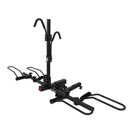
Hollywood Racks Sport Rider Electric Bike Hitch Rack Instruction Manual
Model HR1450E – 2" Hitch
• Not to be used on any
trailer, fifth wheel or vehicle
being towed by another
vehicle
• Weight Limit 80 lbs per bike
• 2 bike maximum capacity
Visit the links below for updates
to this manual:
http://hollywoodracks.com/bike-
racks/hitch-racks/sportrider-hitch-rack-
E.htm
Assembled Support Frame
Model HR1460E – 1 ¼" Hitch
PARTS LIST
Item
Description
A
vertical post
B
main beam
B1
front cap
C
short hook clamp
D
long hook clamp
E
left wheel holder
F
right wheel holder
G
pivot bolt
* Model HR1460E (1 ¼" hitch)
uses threaded locking hitch pin
A
Model HR1450E
shown above
1
Qty
Item
Description
1
H
receiver tube
(1 ¼" or 2" model dependent)
1
I
pivot nut
1
J
pivot washers
1
K
locking hitch pin*
1
L
security cable
2
M
wheel support tube
2
P
"stop" screws
1
R
clip
SUPPORT FRAME
S
straight tube
T
connector tube
U
cross connector
V
front main bracket
Qty
1
1
2
1
1
2
2
2
1
2
2
1
Advertisement

Related Manuals for Hollywood Racks HR1450E


Summary of Contents for Hollywood Racks HR1450E
- Page 1 Hollywood Racks Sport Rider Electric Bike Hitch Rack Instruction Manual Model HR1450E – 2” Hitch Model HR1460E – 1 ¼” Hitch • Not to be used on any PARTS LIST trailer, fifth wheel or vehicle being towed by another Item...
- Page 2 Assembly Instructions: Tools Required: Two 8” adjustable wrenches or equivalent, Phillips screwdriver. For ease of assembly, we suggest that you insert your receiver tube (H) into your vehicle’s hitch. Step 1: Assemble Receiver Tube to Base Assembly a. Install your receiver tube (H) into the hitch.
- Page 3 Step 2: Install Support Frame Fig. 2a SUPPORT FRAME Part# Description straight tube Fig. 2b connector tube cross connector front main bracket a. Remove Front reflector cap using Philips head screwdriver (screw located on bottom of cap) b. Install front main bracket (V). Align hole with tube, then insert pin and clip.
- Page 4 Step 3: Install Wheel Holders Fig. 3a Rotate and remove L pins from holes (A). Rotate wheel tubes to a horizontal position, then replace L pins into holes (B) as indicated. Slide wheel Holders (E and F) onto wheel tubes as indicated. (Fig. 3b) Fig.
- Page 5 Step 5: Fold Up and Tilt Down features Fig. 5a Folding up (Fig. 5a): To fold up the main beam, you must first fold down the vertical post (B). Refer to (Fig. 3a): Rotate and remove pin (A), then rotate the post (B) and replace the pin in either holes (C). Remove snapper pin (H6) from hole (H4) (Fig.
- Page 6 (at its option) a defective part without charge for labor or parts. Hollywood Racks may elect (at its option) to issue a refund equal to the purchase price paid for the product.
Need help?
Do you have a question about the HR1450E and is the answer not in the manual?
Questions and answers