
Related Manuals for DAV TECH DA 400


Summary of Contents for DAV TECH DA 400
- Page 1 Installation and maintenance guide DISPENSING VALVE DA 400 DAV TECH SRL Via Ravizza, 30 - 36075 Montecchio Maggiore (VI) - ITALY Tel. 0039 0444 574510 - Fax 0039 0444 574324 davtech@davtech.it - www.davtech.it...
- Page 2 3.5 Setting of the material quantity 4 MAINTENANCE pag. 6 4.1 General rules 4.2 Valve Disassembly 4.3 Valve Re-assembly 5 TROUBLESHOOTING pag. 6 5.1 Problems and solutions 6 BREAKDOWN AND DIMENSIONS pag. 7 6.1 Breakdown DA 400 6.2 Components 6.3 Overall dimensions DA 400...
-
Page 3: Technical Description
Reproduction of any part of this manual, in any form, without the express written permission of DAV Tech. The text and illustrations in this manual are not binding, the DAV tech reserves the right, at any time and without notice, the right to make any changes to improve the product or for reasons of character manufacturing or commercial. -
Page 4: Installation
screw micrometric Installation and maintenance guide Special versions available on request. 2.3 Connection diagram Connection diagram S.V. 5/2 ALSO POSSIBLE SIMPLE ACTING PRESSURE STABILIZATOR PNEUMATIC PUMP erve the right to modify at any time, without notice, the specifications, dimensions and weights in this datasheet. The illustrations are not binding. 3 INSTALLATION 3.1 Mounting on the machine The valve 400 can be mounted using the through holes present on its body. - Page 5 DISPENSING VALVE DA 400 3.3 Fluid connection The valve must be connected to a power supply unit (tank, pump or other). A hose must be connected to the connector in the lower part of the valve. If you work at pressures above 8 bar use fittings and pipes for high pressure .
-
Page 6: Maintenance
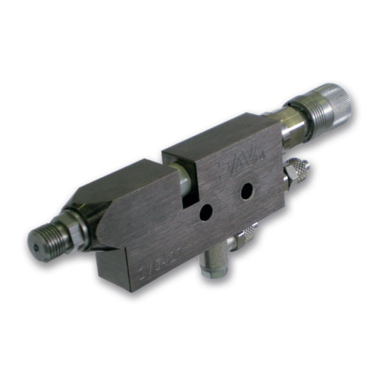
Installation and maintenance guide 4 MAINTENANCE 4.1 Genaral rules The valves DA 400, due to construction methods and materials used, are easy to fig. 1 maintain. Minimal maintenance, simple, accurate and allow a continuous operation lasting over time and adjust the valve, maintaining unchanged performance. - Page 7 DISPENSING VALVE DA 400 6 BREAKDOWN AND DIMENSIONE 6.2 Components 6.1 Valve Breakdown CODE DESCRIPTION 32500002 Complete screw regulation 32500007 Complete micrometric regulation 63700051 Nut screw regulation 32500003 Body screw regulation 92010202 O-ring 32500004 Screw regulation block 92011002 O-ring Adjustment knob...
- Page 8 Download 3D models from our web-site. The size may vary depending on the nozzle used. DAV TECH SRL Via Ravizza, 30 - 36075 Montecchio Maggiore (VI) - ITALY - Tel. 0039 0444 574510 - Fax 0039 0444 574324 davtech@davtech.it - www.davtech.it We reserve the right to modify at any time, without notice, the specifications, dimensions and weights in this manual.
Need help?
Do you have a question about the DA 400 and is the answer not in the manual?
Questions and answers