Advertisement
Quick Links
Advertisement

Subscribe to Our Youtube Channel
Related Manuals for Ceriatone Bluesbreaker JTM45


Summary of Contents for Ceriatone Bluesbreaker JTM45
- Page 1 JTM45 “Bluesbreaker” 35W Amplifier User’s Manual...
-
Page 2: Table Of Contents
Thank you for the purchase of your Ceriatone JTM45 Bluesbreaker guitar amplifier! Here, we hope to explain how best to use your new amp. Table of Contents 1) About the Bluesbreaker …...…………………………………………………………………………………………page 2 2) Quick setup……………………………………………………………………………………………………………page 3 3) Front Panel controls………………………………………………………………………………………………….page 4 4) Rear Panel controls…………………………………………………………………………………………………..page 7... -
Page 3: Quick Setup
2) QUICK SETUP (for instant gratification) 1) Plug your guitar using a 1/4” instrument cable into the upper I input on the right of the front panel 2) Plug a suitable power cable from the Plexi’s rear panel MAINS cable inlet to your wall power receptacle 3) Plug the Plexi into your speaker cabinet using 1/4”... -
Page 4: Front Panel Controls
3) FRONT PANEL CONTROLS From left to right: 1) POWER 2-way toggle switch 2) STANDBY 2-way toggle switch 3) INDICATOR LED 4) SPEED control 5) INTENSITY controll 6) PRESENCE control 7) BASS control 8) MIDDLE control 9) TREBLE control 10) VOLUME I control 11) VOLUME II control 12) INPUT I and II input ¼”... - Page 5 POWER two-way toggle switch powers the JTM45 on and off. With the toggle switch in the DOWN (“ON”) position, the amp is on. In the UP position, the amp is OFF. STANDBY applies high voltage to the vacuum tube anodes (and screen grids) during use of the JTM45. To ensure long tube life, first power the unit on with the STANDBY toggle switch in UP position for approximately 30 seconds.
- Page 6 INPUT I and II are ¼” jacks for instrument cables. Plug your guitar in here. Use the I input for the BRIGHT channel. The BRIGHT channel has more gain, more treble, and a more prototypical JTM45 tone. The UPPER I input is higher gain, whereas the LOWER I input is lower gain.
-
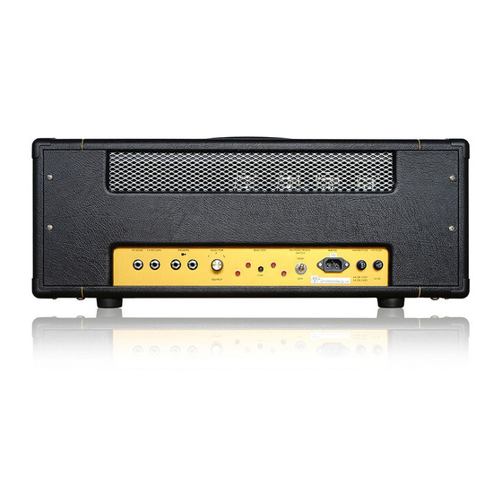
Page 7: Rear Panel Controls
4) REAR PANEL CONTROLS From left to right: 1) SEND ¼” instrument jack 2) RETURN ¼” instrument jack 3) IMPEDANCE SELECTOR three-way rotary selector 4) SPEAKERS ¼” speaker jacks (x2) 5) BIAS TEST probe jacks (x2) 6) COM probe jack 7) FULL / HALF 2-way toggle switch 8) TREMOLO FOOTSWITCH ¼”... - Page 8 IMPEDANCE SELECTOR three-way rotary selector. Set to the position that matches the impedance of your speaker cabinet. NOTE – if you are using two speaker cabinets in parallel (ex – two 16 Ohm cabinets), set the impedance selector to half that of a single cabinet (in this case, 8 Ohms).
-
Page 9: Tube Compliment And Bias Adjustment
5) TUBE COMPLIMENT AND BIAS ADJUSTMENT From left to right: V1 – 12AX7/ECC83 (Input stage Bright and Normal channels) V2 – 12AX7/ECC83 (stage 2 and tonestack cathode follower) V3 – 12AX7/ECC83 (phase inverter for power amplifier) V4 – KT66 V5 – KT66 V0 –... - Page 10 To measure your power tube bias, carefully follow these steps with the amplifier in OPERATE, MASTER at minimum, and connected to a speaker load (not doing so may damage your amplifier!): 1) Turn on a digital multimeter (DMM), and set it to read millivolts (mV) in the 100mV range (this will vary from DMM to DMM) 2) Plug a black probe into the color-coded jack on your DMM, and do the same for a red probe 3) Plug the black probe tip into the COM multimeter jack on the rear of the amp...
- Page 11 An example is as follows: 25�� × 60% × 1000 = ���������� 35���� 420������ You might wonder why your DMM is set to millivolts and not milliamps – simply, we have a 1 Ohm resistor placed between your probe jacks and ground to convert a current reading to a voltage reading. That way, a bias current of 35mA measures as 35mV on your DMM.
- Page 12 Biasing should only be done on a clean workbench with no distractions. Do not wear loose clothing or any jewelry. Take your time, and think carefully before each step. Again, bias at your own risk. Ceriatone Amplification is not responsible for any damages or injuries resulting from user biasing.
-
Page 13: Frequently Asked Questions
6) FREQUENTLY ASKED QUESTIONS How do I hook up this thing? - See Section 2, beginning on page 3. Is the FX loop series or parallel? Active or passive? - The FX loop is series, and is currently passive. However, we have plans to release an option for a tonally transparent solid-state FX loop. - Page 14 Can I substitute different tube types? - Although you can try 12AT7s, 12AU7s, 5751s without any harm, the design is optimized for 12AX7s, and are therefore the only recommended tube in the preamp positions. 5881 tubes are a suitable replacement, but we prefer KT66s for this amplifier.
-
Page 15: Settings Templates
7) Settings templates...
Need help?
Do you have a question about the Bluesbreaker JTM45 and is the answer not in the manual?
Questions and answers