Table of Contents
Advertisement
Quick Links
Advertisement
Table of Contents

Related Manuals for VibroSystM DMV-100


Summary of Contents for VibroSystM DMV-100
- Page 1 DMV-100 Rotor Creep and Speed Detector Installation Manual...
- Page 2 This manual contains information and warnings that must be observed to keep the instruments in a safe condition and ensure safe operation. To use VibroSystM instruments correctly and safely, read and follow all the safety instructions or warnings • given throughout this manual.
-
Page 3: Table Of Contents
INSTALLATION OF THE DMV-100 UNIT General description of the DMV-100 Unit.................... 5.1.1 Overview of the DMV-100 Unit main components ..............Installation of the DMV-100 Unit in a 19” rack or cabinet..............5.2.1 Preliminary considerations for installation in a 19” rack or cabinet ........5.2.2 Required tools and supplies...................... - Page 4 5.3.5 Connecting 4-20 mA Output (RPM) Terminals ............... Initial setup of the DMV-100 System ....................5.4.1 Preliminary considerations......................5.4.2 Setup of the Speed Indicator ..................... DMV-100 Unit - General specifications ....................DMV-100 Rotor Creep and Speed Detector - Installation Manual...
-
Page 5: Overview Of The Dmv-100 Rotor Creep And Speed Detection System
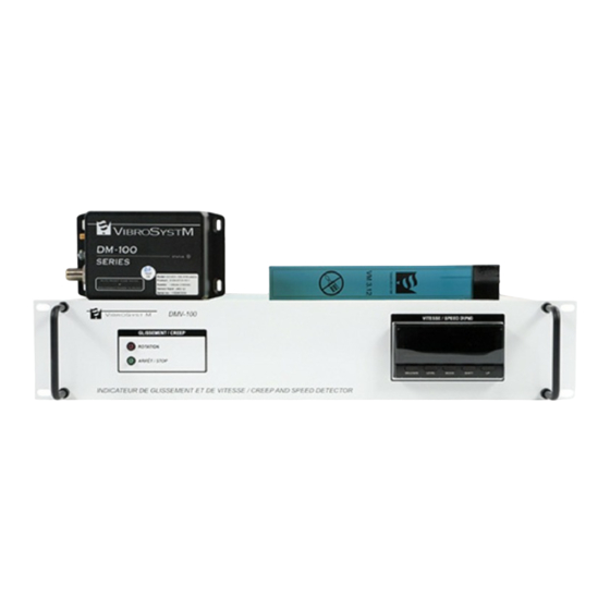
AND SPEED DETECTION SYSTEM Figure 1 : DMV-100 Rotor Creep and Speed Detection complete measuring chain The DMV-100 System is a complete measuring chain for detection of rotor motion (creep) and monitoring of machine rotational speed (RPM). The DMV-100 System is comprised of:... - Page 6 DMV-100 Rotor Creep and Speed Detector - Installation Manual...
-
Page 7: Installation Of The Vm 3.12 Air Gap Sensor For Movement Detection
Handle the sensor with great care. • Never pull on the triaxial cable or on the connector. • Do not apply paint or silicone on the sensor sensing surface. • DMV-100 Rotor Creep and Speed Detector - Installation Manual... -
Page 8: Supplies Needed
The flat portion of a rotor pole is the laminated • steel core or solid steel body, without the plates for mounting the pole to the rotor rim. Sensor beneath second ventilation hole and facing flat portion of rotor DMV-100 Rotor Creep and Speed Detector - Installation Manual... -
Page 9: Step By Step Installation Of The Vm 3.12 Sensor
Finally, you must also apply a fine bead of silicone around the sensor edges and over the integral cable to prevent damage from dirt and particles, and to protect the sensor edges from deterio- ration. DMV-100 Rotor Creep and Speed Detector - Installation Manual... - Page 10 DMV-100 Rotor Creep and Speed Detector - Installation Manual...
-
Page 11: Vm 3.12 Sensor - General Specifications
Dimensions • - Height (sensing surface only) 220.5 mm [8.68 in.] - Width 33.25 mm [1.30 in.] - Thickness 1.77 mm [0.07 in.] - Connector assembly diameter 7.92 mm [0.312 in.] DMV-100 Rotor Creep and Speed Detector - Installation Manual... - Page 12 Coaxial Integral Cable : 50 cm (19.68 ") TOP VIEW 33.25 mm (1.30") 220.50 mm (8.68") SIDE VIEW 3.40 mm (0.13") 1.77 mm (0.07") Figure 4 : Dimensions of the VM 3.12 sensor DMV-100 Rotor Creep and Speed Detector - Installation Manual...
-
Page 13: Installation Of The Triaxial Extension Cable
Use clamps to secure the protective tubing and elbow assembly to the top of the stator. Refer to Figure 7 : “Preparing holes for the cable clamps”. Figure 5 : Securing the protective tubing and coupling DMV-100 Rotor Creep and Speed Detector - Installation Manual... -
Page 14: Supplies Needed
Warning - Danger Caution Triaxial extension cables must be installed on the stator frame or a grounded surface to avoid disrupting the equipotential, and prevent the formation of surface partial discharges and arcing. DMV-100 Rotor Creep and Speed Detector - Installation Manual... -
Page 15: Installation Of Triaxial Extension Cable - Sensor End
* Note: Two ground wires may be present if the sensor cable is also equipped with a ground wire. Figure 8 : Assembly on top of stator frame DMV-100 Rotor Creep and Speed Detector - Installation Manual... - Page 16 Figure 9 : Elbow assembly 4. Slip a piece of heat-shrinkable tubing on the portion of triaxial extension cable sticking out of the protective tubing, Figure 10 : Slipping on a piece of heat-shrinkable tubing DMV-100 Rotor Creep and Speed Detector - Installation Manual...
- Page 17 If the sensor integral cable is equipped with a ground wire, also pull this wire through the protective tubing. Figure 13 : Pulling the SMA connection inside the protective tubing DMV-100 Rotor Creep and Speed Detector - Installation Manual...
- Page 18 Figure 16 : Attaching a grounding wire to the structure through a cable clamp Note: Do not cut or extend the grounding wire. DMV-100 Rotor Creep and Speed Detector - Installation Manual...
- Page 19 Use threadlocker (Loctite 242 or equivalent) to secure the hexagon cap screws (*) Note: Some sensor models have a ground wire. Figure 17 : Securing the cable clamps DMV-100 Rotor Creep and Speed Detector - Installation Manual...
-
Page 20: Silicone Application
To prevent cable deterioration, and dust and debris from entering, apply silicone inside the tubing to form a plug. Figure 18 : Application of silicone DMV-100 Rotor Creep and Speed Detector - Installation Manual... -
Page 21: Installation Of Triaxial Extension Cable - Signal Conditioning Module End
3. Remove the nut, bushing, and inner retainer from the elbow assembly, and install these Bushing components on the sensor end of the flexible conduit. Inner retainer Figure 20 : Flexible conduit connector assembly DMV-100 Rotor Creep and Speed Detector - Installation Manual... -
Page 22: General Specifications Of The Triaxial Extension Cables
Note: Due to the calibration process used, the triaxial cable may be shorter than the specified nominal length. The minimum length of a 10S type cable is 9.5 m [31.2 ft.]. DMV-100 Rotor Creep and Speed Detector - Installation Manual... -
Page 23: Installation Of The Dcc-631 Module For The Dmv-100 System
4. INSTALLATION OF THE DCC-631 MODULE FOR THE DMV-100 SYSTEM 4.1 Preliminary considerations The DCC-631 module is a specialized command instrument which controls an auxiliary power relay to announce rotor movement. An absence of air gap variation over a period of at least 25 seconds... -
Page 24: Installation Of The Dcc-631 Module
2. Use screws and lock washers to firmly set the casing in place. 57.25 mm [2.254"] (Center to center) (Centre à centre) 126.25 mm [4.970"] Figure 24 : Holes location for DCC-631 module DMV-100 Rotor Creep and Speed Detector - Installation Manual... -
Page 25: Connecting The Cable To The Dcc-631
Table 1: DCC-631 module M12 connector configuration Position Wire color Designation Brown +24 V supply White (future use) Blue Common Black Creep detection signal Gray Pulse (1/pole) Shield (ends at M12 connector plastic body DMV-100 Rotor Creep and Speed Detector - Installation Manual... -
Page 26: Led Functionality
Error condition # 2: the LED turns on for one second, followed by two brief flashes, to indicate that the distance to the target is below the minimal detection range. DMV-100 Rotor Creep and Speed Detector - Installation Manual... -
Page 27: Dcc-631 Signal Conditioning Module - General Specifications
M12 socket • Environmental Temperature: • ° to ° ° ° - Operation to 130 ° to ° ° ° - Storage to 185 Humidity Up to 95%, non condensing • DMV-100 Rotor Creep and Speed Detector - Installation Manual... - Page 28 Physical characteristics Module body Die cast aluminium compact casing body • Dimensions • - Height 44.5mm [1.75 in.] - Width 82.5mm [3.25 in.] - Length 139.5mm [5.5 in.] DMV-100 Rotor Creep and Speed Detector - Installation Manual...
-
Page 29: Installation Of The Dmv-100 Unit
In addition to motion detection, the DCC-631 measuring chain sends a 1/pole pulse to the DMV-100 unit for display of real-time machine speed (RPM) through a programmable digital speed display unit. A 4-20 mA RPM-proportional signal output is also available at the back of the DMV-100 unit for remote metering or acqui- sition equipment. -
Page 30: Overview Of The Dmv-100 Unit Main Components
483 W x 305 D x 89 H (mm) 19’’ W x 12’’ D x 3.5’’ H (inches) Figure 26 : DMV-100 Rotor Creep and Speed Detection Unit Figure 27 : Front panel of the DMV-100 rack-mount unit Red LED “Rotation”... - Page 31 A field setup procedure is required prior to operation. The user must enter design-specific information such as the number of poles. The five button keypad allows browsing through display and configuration param- eters. On-screen keywords guide users during setup (refer to 5.4 “Initial setup of the DMV-100 System”). Figure 29 :...
- Page 32 The system is equipped with dual in-line fuse protection in case of power overload. One fuse is provided for each lead to the power supply. Power Input Terminals An internal power supply accepts AC or DC source. This power supply feeds the DMV-100 Unit and the DCC- 631 Conditioner electronics. Protective Conductor Terminal The protective conductor terminal on the rear panel must be connected to a grounding point in compliance with local regulations.
-
Page 33: Installation Of The Dmv-100 Unit In A 19" Rack Or Cabinet
Allow sufficient clearance around the rack or cabinet for maintenance. • The DMV-100 is designed for a 19” rack installation. A rack space of 2U (3.5”) is required. Enclosed racks • must have adequate ventilation, as each component generates heat. An enclosed rack should have enough ventilation and air circulation with help of fans and exhaust at adequate locations to keep enclosed rack pressurized and maintain temperature below 40 ... -
Page 34: Fixing The Dvm-100 Unit To The Rack
(refer to next picture). Figure 30 : Securing the DMV-100 unit to the mounting rails Additional support brackets are available in a variety of configurations. Shown here is an example of adjustable support bracket. -
Page 35: Cabling The Dmv-100 Unit
5.3 Cabling the DMV-100 Unit Warning - Danger Caution The DMV-100 Unit power supply and grounding connection should be installed in accordance with • national and local electrical code. To ensure protection, the chassis grounding wire must be of a heavier gauge than the grounding •... -
Page 36: Connecting The Dcc-631 Conditioner To The Dmv-100 Unit
This connector receives the flying-lead end of the extension cable running from the DCC-631 conditioner to the DMV-100 unit. Five conducting wires and shield must be connected as shown. The power and output cable sends creep detection signals and 1/pole pulses to the DMV-100 rack-mount unit, while the DMV-100 rack-mount unit uses one pair to send +24VDC power to the DCC-631 conditioner. -
Page 37: Connecting The Relay Output (Creep) Terminals
NO and NC contacts, which alternate in the event of creep detection. Figure 33 : Wiring assignment of the 3-position connector to Relay Output (Creep) Figure 34 : Functional diagram of the DMV-100 internal relay DMV-100 Rotor Creep and Speed Detector - Installation Manual... -
Page 38: Connecting 4-20 Ma Output (Rpm) Terminals
RPM limit as configured into the Speed Indicator Max(RPM) = upper RPM limit as configured into the Speed Indicator Linear Output (mA) = reading at 4-20 mA output terminals (see parameters LSet.L and LSet.H in Section 5.4.2.1 “Parameters”) DMV-100 Rotor Creep and Speed Detector - Installation Manual... -
Page 39: Initial Setup Of The Dmv-100 System
Figure 36 : Hysteresis identification The minimum and maximum hysteresis values are factory preset to 46,6 mm and 45,3 mm. DMV-100 Rotor Creep and Speed Detector - Installation Manual... -
Page 40: Setup Of The Speed Indicator
Press the UP key to change the value of the currently displayed parameter • Note: Although the Speed Indicator contains a larger set of parameters, only the setup of parameters used by the DMV-100 application is shown next. DMV-100 Rotor Creep and Speed Detector - Installation Manual... - Page 41 Position meter lower limit -19999 to 99999 LSET.C Linear current model 0 to 20mA, 4 to 20mA LSET.H Linear output upper limit -19999 to 99999 LSET.L Linear output lower limit -19999 to 99999 DMV-100 Rotor Creep and Speed Detector - Installation Manual...
- Page 42 Position meter lower limit: set to 0 (example value) • Linear current model: set to 4-20mA (required value) • Linear output upper limit: set to 135 (example value) • Linear output lower limit: set to 0 (example value) • DMV-100 Rotor Creep and Speed Detector - Installation Manual...
- Page 43 The first set of parameters (Initial setting) will be presented = set of parameters at Level 0 Initial setting FUNC: Function Do not change the setting: the DMV-100 application uses only the F1 func- tion * For reference only, results are displayed as: F1 = RPM / Circumferential speed...
- Page 44 POS-T: Position meter type (OFF, incremental, incremental (reversed)) Press the Shift key to edit the parameter and use the Up key to select incremental. Press the Mode key for next parameter. DMV-100 Rotor Creep and Speed Detector - Installation Manual...
- Page 45 Press the Shift key to edit the parameter and use Up key to select 0. Press the Level key to access the Output test level. This concludes the configuration. Press and hold the Level key at least 3 seconds to return to the Monitor mode. DMV-100 Rotor Creep and Speed Detector - Installation Manual...
- Page 46 Input type • Four types of input signals can be specified. In the DMV-100 application, type 00 is required. For reference only, the input types are: - No-voltage contact (30-Hz max. with ON/OFF pulse width of 15 ms min.);...
- Page 47 Power interruption memory: The measured value can be recorded when the power supply is inter- • rupted. This function is not used by the DMV-100 system and can be set to OFF. DMV-100 Rotor Creep and Speed Detector - Installation Manual...
- Page 48 Position upper limit: set to 135 (example value) • Set maximum RPM for the scale. Position meter lower limit: set to 0 (example value) • Set minimum RPM for the scale DMV-100 Rotor Creep and Speed Detector - Installation Manual...
- Page 49 • Set the corresponding RPM range proportional to the current output through the following parameters: Linear output upper limit: 135 (example value) • Linear output lower limit: 0 (example value) • DMV-100 Rotor Creep and Speed Detector - Installation Manual...
- Page 50 DMV-100 Rotor Creep and Speed Detector - Installation Manual...
-
Page 51: Dmv-100 Unit - General Specifications
0.0005 to 50,000 pulses / sec. (1/Pole) 4-20 mA output • - Linearized signal proportional to programmed RPM scale 500 max. - Output resistive load - Connection Removable 3-screw miniature terminal DMV-100 Rotor Creep and Speed Detector - Installation Manual... - Page 52 Casing 2U, 19” rack-mount • Dimensions • - Height 8.9 cm [3.5 in.] - Width 48.3 cm [19.0 in.] - Depth 30.5 cm [12.0 in.] - Weight 7.25 kg [16 lb] DMV-100 Rotor Creep and Speed Detector - Installation Manual...
Need help?
Do you have a question about the DMV-100 and is the answer not in the manual?
Questions and answers