Sign In
Upload
Manuals
Brands
VibroSystM Manuals
Measuring Instruments
DMV-100
VibroSystM DMV-100 Manuals
Manuals and User Guides for VibroSystM DMV-100. We have
1
VibroSystM DMV-100 manual available for free PDF download: Installation Manual
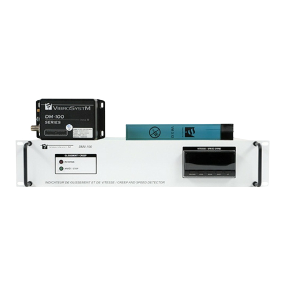
VibroSystM DMV-100 Installation Manual (52 pages)
Rotor creep and speed detector
Brand:
VibroSystM
| Category:
Measuring Instruments
| Size: 3 MB
Table of Contents
Table of Contents
3
1 Overview of the DMV-100 Rotor Creep and Speed Detection System
5
2 Installation of the VM 3.12 Air Gap Sensor for Movement Detection
7
Preliminary Considerations
7
Supplies Needed
8
Positioning the Air Gap Sensor
8
Step by Step Installation of the VM 3.12 Sensor
9
Preparation of Stator Surface
9
Glueing the VM 3.12 Sensor
9
VM 3.12 Sensor - General Specifications
11
3 Installation of the Triaxial Extension Cable
13
Preliminary Considerations
13
Supplies Needed
14
Tools Needed
14
Step by Step Installation of the Triaxial Extension Cable
14
On Site Preparation
14
Installation of Triaxial Extension Cable - Sensor End
15
Silicone Application
20
Installation of Triaxial Extension Cable - Signal Conditioning Module End
21
General Specifications of the Triaxial Extension Cables
22
4 Installation of the DCC-631 Module for the DMV-100 System
23
Preliminary Considerations
23
Installation of the DCC-631 Module
24
Supplies Needed
24
Tools Needed
24
Mechanical Installation of the Casing
24
Connecting the Cable to the DCC-631
25
LED Functionality
26
DCC-631 Signal Conditioning Module - General Specifications
27
5 Installation of the DMV-100 Unit
29
General Description of the DMV-100 Unit
29
Overview of the DMV-100 Unit Main Components
30
Installation of the DMV-100 Unit in a 19" Rack or Cabinet
33
Preliminary Considerations for Installation in a 19" Rack or Cabinet
33
Required Tools and Supplies
33
Fixing the DVM-100 Unit to the Rack
34
Cabling the DMV-100 Unit
35
Connecting the Power Input
35
Connecting the Protective Conductor Terminal
35
Connecting the DCC-631 Conditioner to the DMV-100 Unit
36
Connecting the Relay Output (Creep) Terminals
37
Connecting 4-20 Ma Output (RPM) Terminals
38
Initial Setup of the DMV-100 System
39
Preliminary Considerations
39
Setup of the Speed Indicator
40
DMV-100 Unit - General Specifications
51
Advertisement
Advertisement
Related Products
VibroSystM 797L
VibroSystM 9400-09M3A-101
VibroSystM ZPU-5000
VibroSystM Categories
Measuring Instruments
Diagnostic Equipment
Computer Hardware
Network Hardware
More VibroSystM Manuals
Login
Sign In
OR
Sign in with Facebook
Sign in with Google
Upload manual
Upload from disk
Upload from URL