
Related Manuals for Shure ULX


Summary of Contents for Shure ULX
- Page 1 Shure ULX Wireless The Shure wireless system, ULX, user guide. Version: 3.1 (2020-L)
-
Page 2: Table Of Contents
Shure Incorporated Table of Contents Frequency Display ULX Shure ULX Wireless ULX System Components Frequency Master List Mode Antennas Squelch (ULXP4 Only) Active Antennas Audio Output Antenna Combiners and Accessories Audio Output Connectors Rack Installation Receiver Output Level Rackmount Options... - Page 3 Shure Incorporated Australia Warning for Wireless Specifications Wiring Diagram Frequencies for European Countries 3/31...
-
Page 4: Ulx Shure Ulx Wireless
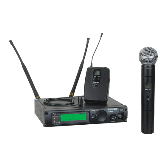
Shure Incorporated ULX Shure ULX Wireless ULX System Components All systems include either a ULXS4 Standard Diversity Receiver or ULXP4 Professional Diversity Receiver. Bodypack systems include a choice of lavalier, headworn, or instrument microphones. Handheld systems include a choice of interchangeable microphone heads. - Page 5 Shure Incorporated Guitar systems include a 1/4” to mini 4-pin cable. ULXP4 receivers include rack-mounting hardware. 5/31...
-
Page 6: Antennas
Antennas Active Antennas The antenna connectors on the ULX receiver provide 12 V DC for active circuit antennas. Caution: Use only Shure antenna accessories to ensure the best operation. Do not use splitters, combiners, or antennas that provide a DC ground, as this can cause the receiver to function improperly. Antenna Combiners and Accessories The supplied antennas can be connected directly to the BNC-type ANTENNA connectors. - Page 7 Shure Incorporated Front Mount Antenna Kit 1/2-Wave Antenna included with ULXP4 systems Inline Antenna Amplifier for long antenna cable runs Antenna Rack Mount Kit 7/31...
-
Page 8: Rack Installation
Shure Incorporated Active Directional Antenna for more focused reception Distribution Amplifier combines antennas and power supplies for multiple receivers Rack Installation 8/31... -
Page 9: Rackmount Options
Shure Incorporated Rackmount Options The following shows rackmounting options for one to four receivers and lists the required accessories. Power 9/31... -
Page 10: Power Switch
Connect using the supplied AC adapter or certified 14–18 Vdc (550 mA) replacement supply. Batteries Installation Battery Life Use only 9V alkaline or lithium batteries. Typical life for common types of 9V batteries are listed below. For detailed information on battery performance, contact Shure Applications Engineering. Recommended: • Lithium (16 hours) • Alkaline (8 hours) Not recommended: •... -
Page 11: Power/Mute Switch
Shure Incorporated • Rechargeable Ni-Cd (2 hours) • Rechargeable Ni-MH (2½ hours) Note: • Battery life varies with type and manufacturer. • Batteries stored for more than a year or stored in excessively hot environments may experience a higher failure rate. -
Page 12: Single System
If using systems from different bands, set up all systems from the same band together. Tip: To reduce setup time, you can manually set up the group and channels before arriving at the venue. Visit www.shure.com for a list of groups and channels that are anticipated to be free of interference in a particular city or region. -
Page 13: Group Scan (Ulxp4 Only)
Shure Incorporated Group Scan (ULXP4 only) The "group scan" feature on the ULXP helps maximize the number of systems you can install at a single venue. It scans for wireless interference and finds the group with the most open channels. -
Page 14: Change Channel
Shure Incorporated Change Channel Change Group * Note: You can reverse the scroll direction by holding SET and pressing MODE. Wireless Indicators RF Indicator Indicates wireless activity over the selected channel. Note: When the antenna and battery indicators are illuminated, the RF indicator shows signal strength from the transmitter. Otherwise, it is showing interfer- ence from another source. Select a different channel. -
Page 15: Antenna Indicator
Shure Incorporated Antenna Indicator This indicator shows which antenna is receiving the strongest signal from the transmitter. Frequency Display For models sold in the United States only. Displays the TV channel occupied by the selected frequency. Frequency Master List Mode Master List mode offers more precise frequency selection for larger, multiple-system installations. -
Page 16: Squelch (Ulxp4 Only)
Shure Incorporated Note: The unit must remain in Master List mode to operate at the selected frequency. Exit Master List mode by holding the SET button for 10 seconds. Squelch (ULXP4 Only) The factory setting offers the optimum performance for most installations. -
Page 17: Receiver Output Level
Shure Incorporated Receiver Output Level Adjusts the level of the receiver's audio outputs. PEAK Icon This icon appears when the input signal overloads the transmitter. The icon is displayed for 2 seconds after input overload is detected. 17/31... -
Page 18: Transmitter Gain
Shure Incorporated Transmitter Gain For best audio quality, adjust transmitter gain so only the green and yellow TX AUDIO LEDs flicker. (Occasional illumination of the red LED is okay.) Green = nominal Yellow = peak Red = overload ULX1 Set the attenuator (pad) switch to 0 dB for microphones and –20 dB for guitars. (Some low output instruments may not need attenuation.) Adjust gain control as necessary. -
Page 19: Ulx2
Shure Incorporated ULX2 • Fully clockwise for quiet to normal vocal performance. • Halfway counterclockwise for loud vocal performance. • Fully counterclockwise for horn or percussive instruments. Locking the Receiver (ULXP4 Only) This feature prevents accidental setting changes. Unlocking Hold the SET button while turning the control wheel left, right, left. -
Page 20: Locking The Transmitter
Shure Incorporated Locking the Transmitter Lock/Unlock Power (On) Hold SET and MODE for four seconds or until the lock icon appears. Lock/Unlock Frequency Hold the SET button while powering on the transmitter. Troubleshooting No power: Check battery and power supply connections and voltage. Check the power switch on the transmitter. -
Page 21: Tips For Improving System Performance
Shure Incorporated Can't turn off or change settings on the transmitter or receiver: The interface is locked. See the section on locking the in- terface. No audio: If the antenna and battery indicators do not appear on the receiver, then it is not receiving a signal from the transmit- ter. Make sure the transmitter and receiver are tuned to the same group and channel. Faint or distorted audio: Adjust transmitter gain, bodypack attenuator switch, and receiver output level. -
Page 22: Replacement Parts
Shure Incorporated UA874X UHF Antenna Power Distribution Amplifier (U.S.A.) UA844SWB UHF Antenna Power Distribution Amplifier (Europe) UA844SWB-E UHF Antenna Power Distribution Amplifier (UK) UA844SWB-UK 33 m (100 ft.) BNC–BNC cable UA8100 1.8 m (6 ft.) BNC–BNC cable UA806 Antenna Rack Panel... -
Page 23: Certifications
Industry Canada ICES-003 Compliance Label: CAN ICES-3 (B)/NMB-3(B) This product meets the Essential Requirements of all relevant European directives and is eligible for CE marking. The CE Declaration of Conformity can be obtained from: www.shure.com/europe/compliance Authorized European representative: Shure Europe GmbH Headquarters Europe, Middle East &... -
Page 24: Important Product Information
Important Product Information LICENSING INFORMATION Licensing: A ministerial license to operate this equipment may be required in certain areas. Consult your national authority for possible requirements. Changes or modifications not expressly approved by Shure Incorporated could void your authority to operate the equipment. Licensing of Shure wireless microphone equipment is the user’s responsibility, and licensability de- pends on the user’s classification and application, and on the selected frequency. Shure strongly urges the user to contact the ... - Page 25 Shure Incorporated Wiring Diagram Specifications RF Carrier Range 470,000–865,000 MHz Working Range 100 m (300 ft) typical Audio Frequency Response 25 Hz – 15 kHz, ±2 dB Modulation ±38 kHz deviation compressor-expander system with pre- and de-emphasis Dynamic Range >100 dB, A-weighted Image Rejection 80 dB, typical 25/31...
- Page 26 Shure Incorporated RF Sensitivity 1.26 µVfor 12 dB SINAD, typical Spurious Rejection 75 dB, typical Ultimate Quieting Ref. ±38 kHz deviation with 1 kHz tone >105 dB, A-Weighted Total Harmonic Distortion Ref. ±38 kHz deviation with 1 kHz tone 0.3%, typical Operating Temperature Range -20°C (-4°F) to 49°C (120°F)
- Page 27 Shure Incorporated ULX2 Gain Adjustment Range 20 dB Dimensions SM58 229 x 51 mm (9 x 2 in.), L x Dia. BETA 58 221 x 51 mm (8.7 x 2 in.), L x Dia. SM86 213 x 49 mm mm (8.4 x 1.9 in.), L x Dia.
- Page 28 Shure Incorporated Frequencies for European Countries G3E 470-506 MHz Country Code Frequency Range Code de Pays Gamme de frequences Codice di paese Gamme di frequenza Código de país Gama de frequencias Länder-Kürzel Frequenzbereich A, B, BG, CH, CY, CZ, D, EST...
- Page 29 Shure Incorporated K2E 606-642 MHz Country Code Frequency Range Code de Pays Gamme de frequences Codice di paese Gamme di frequenza Código de país Gama de frequencias Länder-Kürzel Frequenzbereich A, BG, CH, CY, CZ, D, EST 606 - 642 MHz*...
- Page 30 Shure Incorporated R4 784-820 MHz Country Code Frequency Range Code de Pays Gamme de frequences Codice di paese Gamme di frequenza Código de país Gama de frequencias Länder-Kürzel Frequenzbereich A, B, CH, D, E, F, GB 784 - 820 MHz*...
- Page 31 Shure Incorporated Q2 748-784 MHz Country Code Frequency Range Code de Pays Gamme de frequences Codice di paese Gamme di frequenza Código de país Gama de frequencias Länder-Kürzel Frequenzbereich A, B, CH, D, E, F, GB 748 - 784 MHz*...
Need help?
Do you have a question about the ULX and is the answer not in the manual?
Questions and answers