
Related Manuals for Emerson Daniel 700 Series


Summary of Contents for Emerson Daniel 700 Series
- Page 1 Technical Guide Technical Guide DAN-LIQ-TG-44-rev0813 DAN-LIQ-TG-44-rev0208 November 2013 February 2008 Daniel Liquid Control ® Valves Technical Guide www.daniel.com...
- Page 3 Technical Guide DAN-LIQ-TG-44-rev0813 November 2013 Daniel Measurement and Control Theory, Principle of Operation and Applications This brochure has been prepared to provide a thorough understanding of the principle of operation and typical applications of the Daniel Control Valves. The Daniel Valves operate on a basic hydraulic principle and are of the balanced-piston design, spring biased (loaded). The valves are self contained, pilot operated for most applications (some exceptions) and use the line product as their power source.
-
Page 4: Table Of Contents
Technical Guide DAN-LIQ-TG-44-rev0813 November 2013 Table of Contents Section 1 - AN INTRODUCTION TO BASIC HYDRAULICS ..................3 Pressure Defined ...................................5 Pressure Indicates Work Load ..............................6 Force is Proportional to Pressure and Area ..........................6 Parallel Flow Paths..................................7 Series Flow Paths ..................................7 Pressure Drop Through an Orifice ..............................8 Flow and Pressure Drop ................................9 Fluid Seeks A Level ..................................9... -
Page 5: Section 1 - An Introduction To Basic Hydraulics
Technical Guide DAN-LIQ-TG-44-rev0813 November 2013 Section 1 AN INTRODUCTION TO BASIC HYDRAULICS The study of hydraulics deals with the use and characteristics of liquids. Since the beginning of time, man has used fluids to ease his burden. It is not hard to imagine a caveman floating down a river, astride a log with his wife, and towing his children and other belongings aboard a second log with a rope made of twisted vines. - Page 6 Technical Guide DAN-LIQ-TG-44-rev0813 November 2013 Figure 1-2 shows how Bramah applied Pascal’s principle to the hydraulic press. The applied force is the same as on the stopper in Figure 1-1, and the small piston has the same one square inch area. The larger piston, has an area of 10 square inches. The large piston is pushed on with 10 pounds of force per square inch, so that it can support a total weight or force of 100 pounds.
-
Page 7: Pressure Defined
Technical Guide DAN-LIQ-TG-44-rev0813 November 2013 Pressure Defined: In order to determine the total force exerted on a surface, it is necessary to know the pressure or force on a unit of area. We usually express this pressure in “Pounds per Square Inch”, abbreviated psi. Knowing the pressure and the number of square inches of area on which it is being exerted, one can readily determine the total force. -
Page 8: Pressure Indicates Work Load
Technical Guide DAN-LIQ-TG-44-rev0813 November 2013 Pressure Indicates Work Load: Figure 1-4 illustrates how pressure is generated by resistance of a load. It was noted that the pressure equals the force of the load divided by the piston area. We can express this relationship by the general formula: In this relationship: P is pressure in psi F is force in pounds... -
Page 9: Parallel Flow Paths
Technical Guide DAN-LIQ-TG-44-rev0813 November 2013 Parallel Flow Paths An inherent characteristic of liquids is that they will always take the path of least resistance. Thus, when two parallel flow paths offer different resistances, the pressure will increase only to the amount required to take the easier path. In Figure 1-5 the oil has three possible flow paths. -
Page 10: Pressure Drop Through An Orifice
Technical Guide DAN-LIQ-TG-44-rev0813 November 2013 SERIES RESISTANCES ADD PRESSURE There is no resistance to 0 psi flow here, so ... P4 gauge reads zero. 10 psi Therefore, P3 gauge 10 psi At this point, flow is resisted reads 10 psi. by a spring equivalent to 10 psi. -
Page 11: Flow And Pressure Drop
Technical Guide DAN-LIQ-TG-44-rev0813 November 2013 Flow and Pressure Drop Whenever a liquid is flowing, there must be a condition of unbalanced force to cause motion. Therefore, when a fluid flows through a constant-diameter pipe, the pressure will always be slightly lower downstream than to any point upstream. The difference in pressure or pressure drop is required to overcome friction in the line. -
Page 12: Section 2 - Pressure Versus Variable Force Required
Technical Guide DAN-LIQ-TG-44-rev0813 November 2013 Section 2 PRESSURE VERSUS VARIABLE FORCE REQUIRED Pressure, force, and area were discussed in the Pressure Defined section. It was stated that pressure indicates work load, and force is proportional to pressure and area. The principle described for Figures 2-2 and 2-3 is the same for Figure 1-4, with the exception of the work load. It is, in this instance, a variable force (linear spring). - Page 13 Technical Guide DAN-LIQ-TG-44-rev0813 November 2013 Spring force is 100 pounds (compressed). 0 psi The area is 10 sq. in. 10 sq. in. 10 psi PUMP The pump pressure required equals the spring force divided by area, equals 100 pounds divided by 10 sq. in equals 10 psi for full stroke.
-
Page 14: Section 3 - Basic Valve - No Controls
Technical Guide DAN-LIQ-TG-44-rev0813 November 2013 Section 3 BASIC VALVE - NO CONTROLS The Introduction to Basic Hydraulics covered the subjects of pressure, force and area and how the three are combined to perform various functions. Note the similarity between the spring loaded hydraulic cylinder in Figures 2-2 and 2-3 on Page 11, and the basic control valve in Figures 3-1, 3-2, and 3-3. - Page 15 Technical Guide DAN-LIQ-TG-44-rev0813 November 2013 50% OPEN - The pressure differential across the valve (P1 minus P2) is equal to the spring force in the 50% open position. = Inlet Pressure = Outlet Pressure = Spring Force Figure 3-2 FULLY OPEN - The pressure differential across the valve (P1 minus P2) is equal to the spring force in the fully open position.
-
Page 16: Section 4 - 700 Series Valves
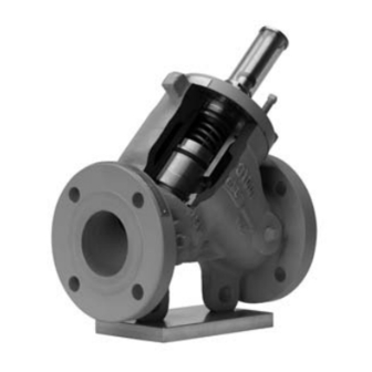
Technical Guide DAN-LIQ-TG-44-rev0813 November 2013 Section 4 700 SERIES VALVES Typical 700 Series Valve This is the starting point for unlimited control applications. The basic valve now incorporates a pilot control loop, which is mandatory for it to function. The basic valve operates on a balanced piston principle, spring biased (loaded). The term balanced piston means that the exposed area on the spring side (P3) of the piston and the bottom side (P1) are equal in area. - Page 17 Technical Guide DAN-LIQ-TG-44-rev0813 November 2013 FULLY OPEN - NO CONTROL - Pilot is fully open. Y-port (P3) is open to Z-port (P2). The pressure on the bottom of the piston (P1) is greater than the pressure at (P3) plus spring force. The valve will not open unless the pressure drop across the valve (P1 minus P2) is slightly greater than the force applied by the main valve spring.
-
Page 18: Model 710 (N.c.), Model 711 (N.o.) Solenoid On-Off Valves
Technical Guide DAN-LIQ-TG-44-rev0813 November 2013 Solenoid Operated On-Off Valves - Model 710 (N.C.) and Model 711 (N.O) N.C. = Normally closed, energize to open N.O. = Normally open, energize to close A solenoid valve is either open or closed. It does not perform any control functions unless the other controls have been incorporated. - Page 19 Technical Guide DAN-LIQ-TG-44-rev0813 November 2013 OPEN POSITION - The solenoid pilot is open. Y-port (P3) is open to Z-port (P2). The pressure on the bottom of the piston (P1) is greater than the pressure at (P3) plus the spring force. (P1 minus P2) is equal to or greater than the spring force.
-
Page 20: Model 750 Pressure Reducing Control Valve (N.o.)
Technical Guide DAN-LIQ-TG-44-rev0813 November 2013 Model 750 Pressure Reducing Control Valve (N.O.) Closes on increasing Outlet Pressure A pressure reducing valve is normally open and throttles toward a closed position on increasing outlet pressure. It is a regulating or positioning type valve that does not require any outside power source to operate. The pilot control is normally open. - Page 21 Technical Guide DAN-LIQ-TG-44-rev0813 November 2013 OPEN - CONTROLLED POSITION - The pilot is partially open. Outlet pressure has slightly exceeded the pilot spring. Z-port (P2) is being squeezed off by the throttling of the pilot, placing higher pressure on Y-port (P3). The increasing pressure at Y-port (P3) plus the main valve spring force, establishes a position of the valve piston so it balances outlet pressure equal to the pilot setting (plus or minus 2 psi).
-
Page 22: Model 760 Back Pressure/761 Pressure Relief Control (N.c.)
Technical Guide DAN-LIQ-TG-44-rev0813 November 2013 Model 760 Back Pressure/Pressure Relief Control (N.C.) Opens on increasing inlet pressure A back pressure/pressure relief valve is normally closed and throttles open on increasing inlet pressure. This valve is used to maintain minimum pressure for more efficient operating conditions or to relieve excess pressure. It is a regulating or positioning type valve that does not require any outside power source to operate. - Page 23 Technical Guide DAN-LIQ-TG-44-rev0813 November 2013 OPEN - CONTROLLED POSITION - The pilot is partially open. Inlet pressure (P1) has slightly exceeded the pilot spring setting. Z-port (P2) is being opened by the throttling of the pilot, reducing the pressure on Y-port (P3). The decreasing pressure at Y-port (P3) plus the main valve spring force establishes a position of the valve piston such that it balances inlet (P1) pressure equal to the pilot setting (Plus or minus 2 psi).
-
Page 24: Model 770 Minimum Differential Pressure Control (N.c.)
Technical Guide DAN-LIQ-TG-44-rev0813 November 2013 Model 770 Minimum Differential Pressure Control (N.C.) Opens on increasing differential pressure The Model 770 valve is normally closed and throttles toward an open position on increasing differential pressure. It is a regulating or positioning type valve that does not require any outside power source to operate. The pilot control is normally closed. - Page 25 Technical Guide DAN-LIQ-TG-44-rev0813 November 2013 OPEN - CONTROLLED POSITION - The pilot is partially open. Differential pressure (P1 minus P4) has slightly exceeded the pilot spring setting. Z-port (P2) is being opened by the throttling of the pilot, reducing the pressure on Y-port (P3). The decreasing pressure at Y-port (P3) plus the main valve spring force establishes a position of the valve piston such that is balances the pump differential pressure (P1 minus P4) equal to the pilot setting (Plus or minus 2 psid).
- Page 26 Technical Guide DAN-LIQ-TG-44-rev0813 November 2013 CLOSED POSITION - Nitrogen gas pressure is higher that the valve inlet pressure, therefore the force of the nitrogen gas plus the spring keep the valve in the closed postition. CLOSED POSITION Pressure Gas Pressure Sensor Gas Pressure Oil Reservoir...
-
Page 27: Model 770 Differential Vapor Pressure Control (N.c.)
Technical Guide DAN-LIQ-TG-44-rev0813 November 2013 Model 770 Differential Vapor Pressure Control (N.C.) Opens on increasing differential pressure Typical for LPG, NH3 or similar products The Model 770 as illustrated is identical to the previously described 770 valve except it is shown as a vapor pressure control valve for products having high flash points such as: butane, propane, anhydrous ammonia or other products with similar characteristics. -
Page 28: Model 762, 763, 765, 766 And 767 Gas Loaded Pressure Relief/Back Pressure Control Valves
Technical Guide DAN-LIQ-TG-44-rev0813 November 2013 Model 762, 763, 764, 765, 766 and 767 Gas Loaded Pressure Relief / Back Pressure Control Valves (N.C.) Open on increasing inlet pressure These valves are normally closed and open upon increasing inlet pressure. They are used to relieve excess surge pressures that may occur during a pipeline upset and can also be used to maintain a minimum back pressure for more efficient operating conditions. - Page 29 Technical Guide DAN-LIQ-TG-44-rev0813 November 2013 OPEN - CONTROLLED POSITION - The pilot is partially open. Differential pressure (P1 minus P4) has slightly exceeded the pilot spring setting. Z-port (P2) is being opened by the throttling of the pilot, reducing the pressure on Y-port (P3). The decreasing pressure at Y-port (P3) plus the main valve spring force establishes a position of the valve piston such that it balances inlet pressure (P1) equal to the pilot setting plus vapor pressure (P4) (Plus or minus 2 psid).
-
Page 30: Model 754 Rate Of Flow Control (N.o.)
Technical Guide DAN-LIQ-TG-44-rev0813 November 2013 Model 754 Rate of Flow Control (N.O.) Closes on increasing differential pressure A rate of flow or flow limiting valve is normally open and throttles toward a closed position on increasing differential pressure (P4 minus P1). It is a regulating or positioning type valve that does not require any outside power source to operate. The pilot control is normally open. - Page 31 Technical Guide DAN-LIQ-TG-44-rev0813 November 2013 OPEN - CONTROLLED POSITION - The pilot is partially open. Differential pressure (P4 minus P1) has slightly exceeded the pilot spring setting. Z-port (P2) is being squeezed off by the throttling of the pilot, placing higher pressure on Y-port (P3). The increasing pressure at Y-port (P3) plus the main valve spring force establishes a position of the valve piston such that it balances differential pressure (P4 minus P1) equal to the pilot setting (plus or minus 2 psid), which is proportional to the flow rate.
-
Page 32: Section 5 - Multiple Pilots (Series And Parallel)
Technical Guide DAN-LIQ-TG-44-rev0813 November 2013 Section 5 MULTIPLE PILOTS (SERIES AND PARALLEL) Model 710S750 Combination Solenoid On-Off and Pressure Reducing Control in Series Both pilots have been illustrated as separate functions on a basic valve (Models 710 and 750). Now the pilots are combined on a single valve. - Page 33 Technical Guide DAN-LIQ-TG-44-rev0813 November 2013 OPEN CONTROLLED POSITION - The solenoid pilot is energized. The pressure reducing pilot is partially open. Outlet pressure has slightly exceeded the pressure reducing pilots spring setting. A-port (P2) is being squeezed off by the throttling of the pressure reducing pilot, placing higher pressure on Y-port (P3).
-
Page 34: Model 710P760 Combination Solenoid On-Off And Back Pressure Control In Parallel
Technical Guide DAN-LIQ-TG-44-rev0813 November 2013 Model 710P760 Combination Solenoid On-Off and Back Pressure Control in Parallel Both pilots have been illustrated as separate functions on a basic valve (Models 710 and 760). Now the pilots are combined on a single valve. When two (2) pilots are in parallel, only one pilot must be open for the main valve to open, but both pilots must close to assure the main valve closes. - Page 35 Technical Guide DAN-LIQ-TG-44-rev0813 November 2013 OPEN CONTROLLED POSITION - The solenoid pilot is closed (de-energized). The back pressure pilot is partially open, bypassing the solenoid pilot. Inlet pressure has slightly exceeded the back pressure pilot spring setting. Z-port (P2) is being opened by the throttling of the pilot, reducing the pressure on Y-port (P3).
-
Page 36: Section 6 - Digital And Two-Stage Electric Shut-Off Valves
Technical Guide DAN-LIQ-TG-44-rev0813 November 2013 Section 6 DIGITAL AND TWO-STAGE ELECTRIC SHUT-OFF VALVES Model 788 DVC Digital Control Electric Shut-off Valves These valves are normally closed (N.C.) and they will open only when both solenoids are energized. The valves are fail-safe as they close upon loss of power. - Page 37 Technical Guide DAN-LIQ-TG-44-rev0813 November 2013 OPEN - CONTROL POSITION - The normally closed solenoid is closed. The normally open solenoid is closed. Y-Port (P3) to Z-port (P2) is closed. X-port (P1) to Y-port (P3) is closed. The product cannot flow to or from the top of the piston.
-
Page 38: Section 7 - Power Cylinder Operated Valves
Technical Guide Technical Guide DAN-LIQ-TG-44-rev0813 DAN-LIQ-TG-44-rev0208 November 2013 February 2008 Section 7 POWER CYLINDER OPERATED VALVES Model 531, 535, 578 and 588 (N.C.) Pressure to Open and Model 532 and 536 (N.O.) Pressure to Close Power cylinder operated valves can perform various functions. The power cylinder can be full open or closed or the pressure can be regulated for two-stage batch control or digital batch control. - Page 39 Technical Guide DAN-LIQ-TG-44-rev0813 November 2013 OPEN POSITION - The differential pressure between (P1) and (P2) has exceeded the total spring force of the power cylinder spring (P1 minus P2). This keeps the valve in a full-open position. Sense Line (HI) Power Sense Cylinder...
-
Page 40: Model 588 (N.c.) Digital Control Electric Shut-Off Valve
Technical Guide DAN-LIQ-TG-44-rev0813 November 2013 DIGITAL CONTROL VALVES Model 588 DVC (N.C.) Digital Control Electric Shut-off Valve Digital Control electric shut-off valves are normally closed (N.C.) and they will open only when both solenoids are energized. The valves are fail-safe as they close upon loss of auxiliary power medium. They use an auxiliary power source (typically regulated instrument air) to open and position the valve. - Page 41 Technical Guide DAN-LIQ-TG-44-rev0813 November 2013 OPEN - CONTROL POSITION - The normally closed solenoid is closed. The normally open solenoid is closed. The power cylinder medium (P3) cannot flow to or from the power cylinder. The piston is pneumatically locked in position until the electronic presets command the valve to open or close as required to maintain the desired flow rate.
-
Page 42: Model 578 (N.c.) Two-Stage Electric Shut-Off Valve
Technical Guide DAN-LIQ-TG-44-rev0813 November 2013 TWO STAGE VALVES Model 578 (N.C.) Two-stage Electric Shut-off Valve Two-Stage Control electric shut-off valves are normally closed (N.C.) and they will open only when both solenoids are energized. The valves are fail-safe as they close upon loss of auxiliary power medium. They use an auxiliary power source (typically regulated instrument air) to open and position the valve for high and low flow. - Page 43 Technical Guide DAN-LIQ-TG-44-rev0813 November 2013 OPEN - HIGH FLOW POSITION - The normally closed solenoid is open. The normally open solenoid is closed blocking the exhaust vent and pressure (P3) is applied to the power cylinder. The pressure on the bottom of the power cylinder piston (P3) is greater than the pressure applied by the spring force, therefore, causing the valve to go full open.
- Page 44 Technical Guide DAN-LIQ-TG-44-rev0813 November 2013...
- Page 45 Emerson Process Management Daniel Measurement and Control, Inc. ("Daniel") is a wholly owned subsidiary of Emerson Electric Co., and a division of Emerson Process Management. The Daniel Measurement and Control, Inc. Daniel name and logo are registered trademarks of Daniel Industries, Inc. The...
Need help?
Do you have a question about the Daniel 700 Series and is the answer not in the manual?
Questions and answers