Table of Contents
Advertisement
Advertisement
Table of Contents

Related Manuals for Xantrex 710-0010


Summary of Contents for Xantrex 710-0010
- Page 1 Owner’s Guide Solar MPPT Remote Panel 710-0010...
- Page 2 Copyright © 2019 Xantrex LLC. All Rights Reserved. All trademarks are owned by Xantrex LLC and its affiliates. Exclusion for Documentation UNLESS SPECIFICALLY AGREED TO IN WRITING, SELLER (A) MAKES NO WARRANTY AS TO THE ACCURACY, SUFFICIENCY OR SUITABILITY OF ANY TECHNICAL OR OTHER INFORMATION PROVIDED IN ITS MANUALS OR OTHER DOCUMENTATION; (B)
-
Page 3: Important Safety Information
IMPORTANT SAFETY INFORMATION ’ READ AND SAVE THIS WNER UIDE FOR FUTURE REFERENCE Read these instructions carefully and look at the equipment to become familiar with the device before installing, operating, configuring, maintaining, and troubleshooting it. The following special messages may appear throughout this documentation or on the equipment to warn of potential hazards or to call attention to information that clarifies or simplifies a procedure. -
Page 4: Product Safety Information
Product Safety Information 1. Before using the remote panel, read all instructions and cautionary markings on the remote panel's components, the batteries, and all appropriate sections of this guide. 2. Use of accessories not recommended or sold by the manufacturer may result in injury to persons, a risk of electric shock, or a risk of fire. - Page 5 DANGER HAZARDORFIRE,ELECTRICALSHOCK,EXPLOSION,ORARCFLASH This Xantrex SOLAR MPPT Remote Panel Owner's Guide is in addition to, and incorporates by reference, the relevant product manuals for each product in the power system. After reviewing this guide you must read the relevant product manuals. Unless specified, information on safety, specifications, installation, and operation is as shown in the primary documentation received with the product.
- Page 6 CAUTION EQUIPMENT DAMAGE Do not integrate this remote panel with a residential electrical system. Failure to follow these instructions can result in injury or equipment damage. 975-1013-01-01 Rev A Oct 2019...
-
Page 7: End Of Life Disposal
Many of the electrical components used in the Xantrex SOLAR MPPT Remote Panel are made of recyclable material like steel, copper, aluminum, and other alloys. These materials can be auctioned off to traditional scrap metal recycling companies who resell reusable scraps. -
Page 8: Table Of Contents
Contents Important Safety Information Product Safety Information End of Life Disposal Materials List Basic Installation Steps Unit Features Remote Panel LCD Display and Function Buttons Status Icons Event Indicators Operation Using the Remote Panel Automatic Status Display Screens Specifications Mounting Template 975-1013-01-01 Rev A Oct 2019... -
Page 9: Materials List
2 Owner's Guide 3 Mounting screws (#4 x 3/8" wood screws) Menu Up / Set Power NOTE: If any of the items are missing, contact Xantrex or any authorized Xantrex dealer for replacement. See Contact Information on page 1. Basic Installation Steps 1. - Page 10 Figure 1 Preparing for mounting o w e r e t P U p / S M e n u 1 Using the mounting template at the end of this guide, mark the positions of the center hole and the mounting holes on the wall where you plan to mount the remote panel. 2 Using a hole saw with a minimum diameter of 3"...
- Page 11 1 PV panel Panel cable 2 Solar charge controller Pos [+] Battery cable with battery fuse Battery 3 Xantrex SOLAR MPPT Remote Panel 9 4 DC equipment ground Neg [–] Battery cable 5 Pos [+] PV cable with PV disconnect DC battery / Chassis ground device 6 Neg [–] PV cable...
-
Page 12: Unit Features
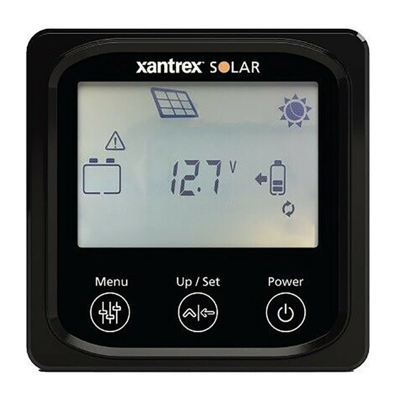
Unit Features Menu Up / Set Power LCD display MENU button UP / SET button Power [Standby] button Remote port Mounting holes 975-1013-01-01 Rev A Oct 2019... -
Page 13: Remote Panel Lcd Display And Function Buttons
Remote Panel LCD Display and Function Buttons Button Action Description Allows you to: Menu browse devices such as BAT1, PV, and BAT2 Short press browse settings for each device show automatic status display setting 975-1013-01-01 Rev A Oct 2019... - Page 14 Button Action Description Allows you to: browse PV Array settings Short press browse BAT1 settings Up / Set browse BAT2 settings configure the temperature unit configure the battery type Long press (5 sec) en/disable automatic status display Power Short press Turn on the Remote panel screen Long press (5 Turn off the Remote panel screen...
-
Page 15: Status Icons
Status Icons Icon Description Icon Description BAT1 SOC BAT2 SOC 0~12% 0~12% BAT1 SOC BAT2 SOC 13~35% 13~35% BAT1 SOC BAT2 SOC 36~61% 36~61% BAT1 SOC BAT2 SOC 62~86% 62~86% BAT1 SOC BAT2 SOC 87~100% 87~100% BAT1 Charging BAT2 Charging Daytime Nighttime Display BAT1 parameters Display BAT2 parameters PV Panel Display PV parameters 975-1013-01-01 Rev A Oct 2019... - Page 16 Icon Description Icon Description BAT1 temperature Battery type Settings (Parameters) Minimum voltage Auto screen cycle Maximum voltage Event 975-1013-01-01 Rev A Oct 2019...
-
Page 17: Event Indicators
Event Indicators NOTE: When an event is detected the LED indicators flash and the individual icons on the LCD Display also flash. LCD Icon/s Event Description Over-charging event on BAT1 Over-charging event on BAT2 BAT1 discharged BAT2 discharged Over-temperature event on BAT1 BAT1 charging voltage outside of range BAT2 charging voltage outside of range BAT1 and/or BAT2 batteries are not connected. -
Page 18: Operation Using The Remote Panel
Operation Using the Remote Panel To browse different devices and their settings: Power 1. Short press to turn on the panel. Menu 2. Press repeatedly to display each device screen. Power 3. Short press to turn off the panel screen. NOTE: Pressing this button does not turn off the solar charger unit, only the display panel screen. - Page 19 To enable automatic status display: Power 1. Short press to turn on the panel, if not already on. Menu 2. Press once to display Auto. Up / Set 3. Press and hold for 5 seconds until appears. After 2 seconds each device setting will be displayed in sequence every 2 seconds.
- Page 20 To change the temperature unit setting: Power 1. Short press to turn on the panel, if not already on. Menu 2. Press repeatedly until the BAT1 device screen is displayed. Up / Set 3. Press repeatedly until the temperature, the icon, and the icon are displayed.
- Page 21 To change the battery type setting: Power 1. Short press to turn on the panel, if not already on. Menu 2. Press repeatedly until the BAT1 (or BAT2 ) device screen is displayed. Up / Set 3. Press repeatedly until the current battery type, the icon, and the icon are displayed.
- Page 22 To reset the PV Harvest: Power 1. Short press to turn on the panel, if not already on. Menu 2. Press repeatedly until the PV device screen is displayed. Up / Set 3. Press repeatedly until the cumulative PV Harvest status ...
-
Page 23: Automatic Status Display Screens
Automatic Status Display Screens → → → → → start Shows input PV voltage. Shows input PV current. Shows input PV power. → → → → → → Shows cumulative PV Harvest Shows battery 1 (BAT1) Shows BAT1 current. -
Page 24: Specifications
Specifications NOTE: Specifications are subject to change without prior notice. Specifications Solar MPPT Remote Panel Part number 710-0010 Power consumption 10mA/5VDC Minimum power consumption Operating temperature -20 – 70 °C (-4 – 158 °F) Storage temperature -20 – 70 °C (-4 – 158 °F) -
Page 25: Mounting Template
Mounting Template NOTE: You may tear the next page. 3” (76.2mm) 3.5” (88.9mm) NOTE: Markthe positionsof the center hole and the mounting holeson the wallwhere you plan to mount the remote panel. Use a hole saw with a minimum diameter of 3" (76.2mm) and a maximum of 3.5"(88.9mm) to cut a circular hole on the wall. - Page 27 This page has no content.
- Page 28 +1-800-670-0707 +1-408-987-6030 customerservice@xantrex.com http://www.xantrex.com/power-products-support/ http://www.xantrex.com 975-1013-01-01 Rev A Printed in Oct 2019...
Need help?
Do you have a question about the 710-0010 and is the answer not in the manual?
Questions and answers
I just purchased a travel trailer with this set up. What do I need to do to make sure I have the settings done correctly to maximize the battery life with the solar panel?