
Related Manuals for Xantrex XW-SCP 865-1050


Summary of Contents for Xantrex XW-SCP 865-1050
-
Page 1: Control Panel
Standby Fault/Warning System Control Panel II Owner’s Guide XW System Control Panel... - Page 3 XW System Control Panel Owner’s Guide...
- Page 4 Trademarks XW System Control Panel is a trademark of Xantrex International. Xantrex and Xanbus are registered trademarks of Xantrex International. Other trademarks, registered trademarks, and product names are the property of their respective owners and are used herein for identification purposes only.
-
Page 5: About This Guide
System Control Panel. Installers should be certified technicians or electricians. Organization This Guide is organized into five chapters and one appendix. Chapter 1, “Introduction”, introduces and describes features of the Xantrex System Control Panel. Chapter 2, “Installation”, contains information and procedures for installing the System Control Panel. - Page 6 XW Series Hybrid Inverter/Charger Operation Guide (975-0240-01-01) XW Series Solar Charge Controller Owner’s Manual (975-0283-01-01) XW Automatic Generator Start Owner’s Guide (975-0307-01-01) You can find more information about Xantrex Technology Inc. as well as its products and services at www.xantrex.com. 975-0298-01-01...
-
Page 7: Important Safety Instructions
Important Safety Instructions WARNING: Save these instructions This Owner’s Guide contains important safety and operating instructions. Before using your XW System Control Panel, be sure to read, understand, and save these safety instructions. General Precautions 1. Before installing and using this device, read all appropriate sections of this guide and any cautionary markings on the System Control Panel and the devices to which it connects. - Page 8 FCC Information to the User This equipment has been tested and found to comply with the limits for a Class B digital device, pursuant to part 15 of the FCC Rules. These limits are designed to provide reasonable protection against harmful interference when the equipment is operated in a residential environment.
-
Page 9: Table Of Contents
Contents Important Safety Instructions - - - - - - - - - - - - - - - - - - - - - - - - - - - - - - - - - - -v 1 Introduction About the XW System Control Panel - - - - - - - - - - - - - - - - - - - - - - - - - - - - - - - - - 1–2 Physical Features - - - - - - - - - - - - - - - - - - - - - - - - - - - - - - - - - - - - - - - - - - - - - - 1–3 Front Panel Features - - - - - - - - - - - - - - - - - - - - - - - - - - - - - - - - - - - - - - - - - 1–3... - Page 10 Contents Setting the Time - - - - - - - - - - - - - - - - - - - - - - - - - - - - - - - - - - - - - - - - - - 3–11 Setting the Date - - - - - - - - - - - - - - - - - - - - - - - - - - - - - - - - - - - - - - - - - - - 3–12 Using the System Settings Menu- - - - - - - - - - - - - - - - - - - - - - - - - - - - - - - - - - - 3–12 System Settings Menu Configuration Items - - - - - - - - - - - - - - - - - - - - - - - - 3–13...
-
Page 11: Introduction
Introduction Chapter 1 introduces and describes operational and physical features of the XW System Control Panel. -
Page 12: About The Xw System Control Panel
Enables you to adjust settings for each Xanbus-enabled device. System The System Control Panel uses Xanbus™, a network communications component protocol developed by Xantrex, to communicate its settings and activity to other Xanbus-enabled devices. Xanbus-enabled products are: • Easy to use. The Xanbus network simplifies operation and automates routine tasks. -
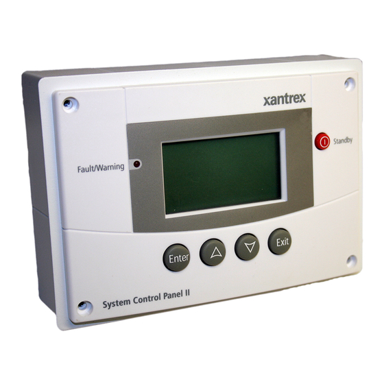
Page 13: Physical Features
Physical Features Physical Features See Figure 1-1 and Figure 1-2 for the front and back features of the System Control Panel. Front Panel Features Standby Fault/Warning System Control Panel II Figure 1-1 Front Panel Feature Fault/Warning light indicates a device has a fault or warning condition and requires attention. -
Page 14: Back Panel Features
Introduction Back Panel Features Two Xanbus network inputs on the back panel let you connect the System Control Panel to other Xanbus-enabled devices. See Figure 1-2. Xanbus network inputs (8-pin RJ-45) Figure 1-2 Back Panel System Components The Xanbus system (Figure 1-3) includes the System Control Panel and other Xanbus-enabled devices. -
Page 15: Installation
Installation Chapter 2 contains information and procedures for planning and performing a XW System Control Panel installation, including: • Materials and tools required • Choosing a location • Choosing a network layout • Mounting the unit • Connecting the System Control Panel to other devices. -
Page 16: Installing The Xw System Control Panel
Installation Installing the XW System Control Panel The XW System Control Panel is designed to be wall mounted (see “Mounting the System Control Panel” on page 2–11), and requires no connections other than Xanbus network cables or a terminator plugged into the back of the unit. -
Page 17: Network Installation
Xanbus power supply—the network requires a power supply capable of providing 15 Vdc/200 mA to each device. The XW Series Inverter/ Charger provides network power, but if no inverter/charger is installed, an external power supply is required. Contact Xantrex for more information. •... - Page 18 If the network is not properly terminated, signal quality is degraded and performance on the network is reduced. Permanent configuration without terminators is not supported by Xantrex. The System Control Panel ships with one male terminator already installed. Depending on your network layout, this terminator may need to be removed and inserted into another device elsewhere in the network.
- Page 19 Network Installation Male network terminator Female network terminator Figure 2-3 Network Terminators • Network connectors (optional, depending on network layout)—the three-way connector houses three RJ-45 inputs that provide a device connection point on a multi-drop backbone layout (see “Multi-Drop Backbone Layout” on page 2–6). All three inputs are wired identically and can accept either Xanbus cables or terminators.
-
Page 20: Ordering Network Components
Ready-made cables are available in standard lengths from 3 feet to 75 feet. For the most up-to-date list, call your dealer. Call your dealer or visit the Outlet Store at www.xantrex.com to purchase cables and other network components. Table 2-1 Network Components and Part Numbers... - Page 21 Network Installation Network terminators are required at both ends of the network, and the Xanbus-enabled devices do not require their own termination. If cables are placed at the end of the network, female terminators are required. Otherwise, male terminators must be inserted directly into the open input of each network connector at the end of the network.
-
Page 22: Guidelines For Routing The Xanbus Cables
Installation Disadvantage The disadvantage of the daisy chain layout is that Xanbus-enabled devices cannot be removed from the network without interrupting the network. To make the network function after removing a device, you must connect the Xanbus-enabled devices on either side of the missing device to each other or replace the device. -
Page 23: Connecting Xanbus Cables
Network Installation • Keep the alignment of wire pairs inside the sheath as straight as possible. • Allow separation between data and power cables (data cables should only cross a power cable at right angles). • Do not staple the cable with metal cable staples. Use appropriate hardware fasteners to avoid damage to the cable. - Page 24 Installation Multi-Drop Backbone Layout To connect Xanbus cables to the System Control Panel: 1. Install one network connector for the System Control Panel and each Xanbus-enabled device. 2. Connect a Xanbus cable from the nearest network connector to a Xanbus network input in the System Control Panel. 3.
-
Page 25: Mounting The System Control Panel
Mounting the System Control Panel Mounting the System Control Panel The System Control Panel can be mounted three ways: • Flush mounted through an opening in a wall using the mounting plate • Surface mounted using the mounting bracket • Flush mounted through an opening in a wall and secured with four #6 screws. - Page 26 Installation Rotate tabs to horizontal position Figure 2-8 Securing the Mounting Plate 5. Connect the Xanbus cable(s) (and terminator if necessary) to either network input on the back of the System Control Panel. See Figure 2-9. Connect a network terminator to the System Control Panel if it is the last device at the end of a daisy chain network layout.
- Page 27 Mounting the System Control Panel 6. Place the unit into the mounting plate and secure it with four #6 screws. Figure 2-10 Securing the System Control Panel 7. Peel off the protective plastic coating covering the screen and indicator light. To flush mount the System Control Panel with no mounting plate: 1.
- Page 28 Installation To surface mount the System Control Panel: 1. Using the supplied template sticker as a guide, mark the locations for two mounting screws and the access hole for the Xanbus cables. 2. Using a hole saw, cut out the access hole for the Xanbus cable(s). 3.
-
Page 29: Verifying The Installation
Verifying the Installation Verifying the Installation If network power (from an inverter/charger or external power supply) is present, the backlight will come on and the System Control Panel will show the startup screen (see page 3–3). When the System Control Panel is started up on the Xanbus system for the first time, it displays a fault message asking you to set the clock before proceeding. - Page 30 2–16...
-
Page 31: Configuration
Configuration Chapter 3 contains guidelines for configuring the XW System Control Panel and for using the XW System Control Panel to configure other Xanbus-enabled devices. This chapter does not recommend specific settings for devices on your system. For device configuration information, refer to the Owner’s Guide or Operation Guide for each Xanbus-enabled device. -
Page 32: Configuration Using The System Control Panel
Configuration Configuration Using the System Control Panel The System Control Panel can display and change the settings for any Xanbus-enabled device in the Xanbus system. Using System Control Panel Buttons The System Control Panel has four buttons for: • moving between status screens and menus •... - Page 33 Configuration Using the System Control Panel Appears for a few seconds after the system starts up or when the system has been reset. Startup screen Select device from System Status Select Device list and press Enter System Press Enter to Select Device to view Device Status screen...
- Page 34 Configuration Important: If you are uncertain which System Control Panel screen or menu you are viewing, you can always return to the starting point—the System Status screen—by pressing Exit until the System Status screen appears. XW Inverter/Charger Home Screen The XW Inverter/Charger Home screen is the first of the Device Home screens.
-
Page 35: Changing Settings For A Device
Configuration Using the System Control Panel Device Setup Menus Device Setup menus display status information and changeable settings. Changeable settings are identified by the square brackets [ ] around values in the right-hand column. To display the Setup menu for a device: u On the Select Device menu, highlight the device name and press Enter. - Page 36 Configuration WARNING: Risk of fire and shock hazard The Advanced settings for devices other than the System Control Panel are intended for qualified installation/service personnel only. Before changing advanced settings, you must be familiar with the settings and the system-wide impact of changing those settings.
-
Page 37: Configuring The Xw System Control Panel
Configuring the XW System Control Panel 3. Press the up arrow or the down arrow button to change the value. Hold down the button to scroll through a large range of values quickly. 4. Press Enter to select the value or Exit to cancel the value selection. 5. -
Page 38: System Control Panel Configuration Items
Configuration System Control Panel Configuration Items The SCP Setup menu contains settings for changing the appearance of the display, enabling button-press and alarm sounds, and setting the temperature scale. Items in gray appear only on the advanced menu. Menu item Description Values/Action Default... -
Page 39: Setting The Device Name
Configuring the XW System Control Panel Setting the Device Name The “Name” setting allows you to customize the name of the System Control Panel as it is displayed on other screens and menus. The characters available are: • A to Z •... -
Page 40: Using The Clock Menu
Configuration Using the Clock Menu Use the Clock menu to set the clock, the date, and the time format you prefer. The clock is listed as a separate device on the Select Device menu. To view the Clock menu: u On the Select Device menu, highlight Clock and press Enter. Select Device Clock [2:55PM]... -
Page 41: Setting The Time
Using the Clock Menu Setting the Time Because the System Control Panel keeps time for the power system, setting the clock to the correct local time is essential for the system to operate as expected. The clock also provides the time stamps for the Warning and Fault logs. -
Page 42: Setting The Date
Configuration Setting the Date You can set the reference date for the Xanbus system from the Clock menu. To set the date: 1. On the Clock menu, press the up arrow or down arrow button to highlight Set Date. 2. Press Enter to highlight the month. 3. -
Page 43: System Settings Menu Configuration Items
Using the System Settings Menu System Settings Menu Configuration Items Menu item Description Values/Action Default Invert Enables or disables inverting for all inverters Enabled, Disabled Enabled in the system. Press Enter to view and select values. AC Charge Enables or disables charging on AC input for Enabled, Disabled Enabled all inverter/chargers in the system. -
Page 44: Using Cascading Parameters
Configuration Using Cascading Parameters Xanbus-enabled devices are configured one at a time. However, because devices often have common settings, cascading parameters can simplify and speed up system configuration. When a parameter is “cascaded,” a newly configured device setting is applied to all devices of the same device type on a common AC or DC connection. - Page 45 Using the System Settings Menu 2. Press the down arrow button to view information for each Xanbus- enabled device on the system. 3. Press Exit to return to the System Settings menu. 975-0298-01-01 3–15...
- Page 46 3–16...
-
Page 47: Operation
Operation Chapter 4 contains information and procedures for operating the XW System Control Panel, including: • System modes • Faults and warnings... -
Page 48: System Modes
Xanbus-enabled devices is disabled and all inverting, charging, and generator starting activity stops. Selecting Standby mode stops the generator (if it is running and a Xantrex Automatic Generator Start is part of the system) and puts the System Control Panel (and all Xanbus-enabled devices) into Standby mode. -
Page 49: Using The Standby Button
Warnings and Faults Using the Standby Button Pressing the Standby Button produces the same result as disabling “Invert” and “AC Charge” from the System Settings menu on the System Control Panel. Pressing the Standby button does not affect Charge Controller operation. After disabling inverting and charging with the Standby button, the system continues to pass AC input through to the loads. - Page 50 Operation Warning: W250 continue cancel Figure 4-1 System Control Panel warning message Types There are two types of warning messages: manual and automatic. Each differs in its behavior and appearance. For a list of System Control Panel warnings and their associated types, refer to Chapter 5, “Troubleshooting”.
- Page 51 Warnings and Faults Clearing Warning Messages Automatic warning messages clear when the warning condition on the System Control Panel disappears or when the criteria for clearing the warning are met. You can clear a manual warning message by pressing Enter or Exit in response to the message.
-
Page 52: Fault Messages
Operation To view the warning log: 1. On the SCP menu, press the down arrow button to highlight View Warning Log. 2. Press Enter. To return to the SCP menu: u From the Warning log, press Exit. Warning Log:SCP Figure 4-2 System Control Panel warning log Viewing Individual Warning Messages from the Warning Log On the warning log, you can also select an individual warning and view its details. - Page 53 Warnings and Faults Fault: F504 continue cancel Figure 4-3 System Control Panel fault message Types of fault There are two types of System Control Panel fault messages: automatic and manual. For a list of faults and their associated types, refer to Chapter messages 5, “Troubleshooting”.
- Page 54 Operation To return to the SCP menu: u Press Exit. Viewing Individual Fault Messages from the Fault Log On the fault log, you can also select an individual fault and view its details. To view details for a fault: 1. Use the up arrow or down arrow button to highlight the fault message you want to view.
- Page 55 Warnings and Faults You can also view the fault list at any time. To view the fault list at any time: 1. On the Select Device menu, use the up arrow or down arrow button to highlight System Settings. 2. Press Enter. 3.
- Page 56 4–10...
-
Page 57: Troubleshooting
Troubleshooting Chapter 5 contains reference tables of warning and fault messages that relate to the System Control Panel. For information about warning and fault messages that relate another device, see the guide for that device. Use these tables to help you identify the cause of the fault or warning, and determine the best course of action to correct the condition that caused the fault or warning. -
Page 58: Troubleshooting Reference
Troubleshooting Troubleshooting Reference Types of Faults and Warnings The various types of fault and warning messages behave differently, and give you the option to treat them differently when they appear. For more information about the types of fault and warning messages, see “Types” on page 4–4 and “Types of fault messages”... - Page 59 Troubleshooting Reference Table 5-1 Warning Reference Table Warning number Message Type Cause Action W255 System clock not Manual On initial startup, the clock Set the clock to the correct set. Set correct time. needs to be set. The system time. See “Using the Clock will not operate correctly Menu”...
-
Page 60: Fault Reference Table
Troubleshooting Fault Reference Table Table 5-2 Fault Reference Table Fault number Message Type Cause Action F250 System clock not Manual On initial startup, the clock Set the clock to the correct set. Set correct needs to be set. The system time. - Page 61 Troubleshooting Reference Table 5-2 Fault Reference Table Fault number Message Type Cause Action F505 Internal failure. Manual A controller fault has Reset the System Control See guide. occurred and the System Panel by removing and Control Panel has gone into restoring network power.
- Page 62 5–6...
- Page 63 Specifications Appendix A contains the electrical and physical specifications for the XW System Control Panel. All specifications are subject to change without notice.
-
Page 64: Electrical Specifications
Specifications Electrical Specifications Nominal input network voltage 15 Vdc Minimum operating network voltage 14.25 Vdc Maximum operating network voltage 15.75 Vdc Maximum operating current 200 mA @ nominal input network voltage Communication physical layer 2, CAN Communication protocol Xanbus Maximum cable length 130 ft (40 m) Connectors 2 RJ-45—8 pins... - Page 65 Environmental Specifications 3 ½ [77] 1/32 [90] [102] 13/32 5 ½ [140] 1 [24] [10] 6 [152] [30] 3/16 ALL DIMENSIONS IN INCHES [mm] 5 [127] 1/8 [3] TYP. Figure A-1 System Control Panel Dimensions 975-0298-01-01 A–3...
- Page 66 A–4...
-
Page 67: Warranty And Return Information
What will Xantrex do? Xantrex will, at its option, repair or replace the defective product free of charge, provided that you notify Xantrex of the product defect within the Warranty Period, and provided that Xantrex through inspection establishes the existence of such a defect and that it is covered by this Limited Warranty. - Page 68 Xantrex product specifications including high input voltage from generators and lightning strikes; c) the product if repairs have been done to it other than by Xantrex or its authorized service centers (hereafter "ASCs"); d) the product if it is used as a component part of a product expressly warranted by another manufac- turer;...
- Page 69 SUPPORT SYSTEMS OR OTHER MEDICAL EQUIPMENT OR DEVICES. Return Material Authorization Policy Before returning a product directly to Xantrex you must obtain a Return Material Authorization (RMA) number and the correct factory "Ship To" address. Products must also be shipped prepaid. Product...
- Page 70 MUST include return freight funds and are fully responsible for all documents, duties, tariffs, and deposits. If you are returning a product to a Xantrex Authorized Service Center (ASC) A Xantrex return material authorization (RMA) number is not required. However, you must contact the ASC prior to returning the product or presenting the unit to verify any return procedures that may apply to that particular facility.
- Page 71 Warranty and Return Information About Your System As soon as you open your XW System Control Panel package, record the following information and be sure to keep your proof of purchase. p Product Number 865-1050 p Serial Number _________________________________ p Purchased From _________________________________ p Purchase Date _________________________________...
- Page 72 WA–6...
-
Page 73: Index
Index Numerics 1–3 fault light 3–13, 4–8 Fault list 3–10 12/24 Hour 3–8, 4–7 Fault log fault messages 3–8 clearing 3–6 4–6 Advanced menu types 5–4 fault reference table 3–14 firmware revision 3–8 backlight timer 3–8 brightness 3–8 WA–5 Button Beep Information about Your System form installation 2–12... - Page 74 Index WA–5 1–2 proof of purchase Xanbus WA–5 purchase date Xantrex web site 3–5 device menu 3–4 select device menu WA–5 serial number 3–10 Set Date 3–8 Set Degrees 3–10 Set Time A–2 specifications 1–3, 4–3 standby button 4–2 Standby mode 3–3...
- Page 76 Xantrex Technology Inc. 1 800 670 0707 Tel toll free NA 1 360 925 5097 Tel direct 1 800 994 7828 Fax toll free NA 1 360 925 5143 Fax direct customerservice@xantrex.com www.xantrex.com 975-0298-01-01 Printed in Canada...
Need help?
Do you have a question about the XW-SCP 865-1050 and is the answer not in the manual?
Questions and answers