Table of Contents
Advertisement
Quick Links
PHOTOELECTRIC
DUAL BEAM DETECTOR
Owners Manual
R4222
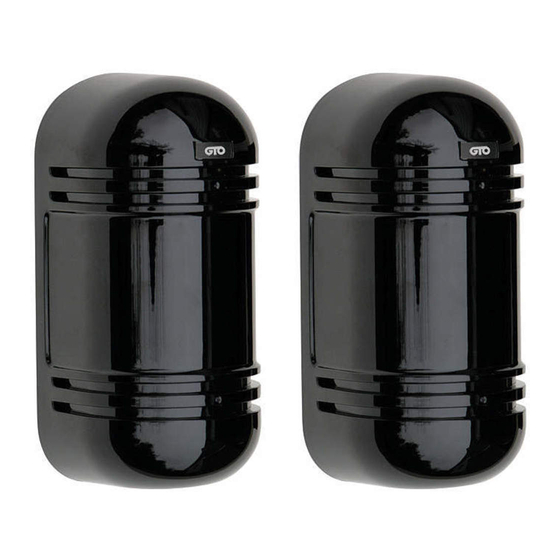
The GTO Access Systems Photoelectric Dual Beam Detector uses dual beam and through-beam technology
to reduce false detections when detecting obstructions. When the beams detect the presence of a moving
object, the detection will cause the gate(s) to stop and reverse to the fully open position. As long as the
beam is obstructed the gate(s) will remain open. Not compatible with solar powered gate operators.
PARTS DESCRIPTION
For more information on GTO's full line of automatic gate openers and access controls visit our website at www.gtoaccess.com
GTO Access Systems • 3121 Hartsfield Road • Tallahassee, Florida 32303 • (800) 543-4283 • www.gtoaccess.com
R4222
Rev. 03/16/15
Printed in China for GTO Access Systems
For use with all GTO Access Systems and Mighty Mule gate operators.
COVER
Technical Service (800) 543-1236
INTERNAL VIEW OF RECEIVER
Wiring Hole
Connection
Terminals
Indicator
Lights
Vertical
Alignment
Screw
Sight Hole
Lens
Optical Alignment
Indicator
Tamper Switch
Horizontal Angle
Adjustment Bracket
Cover Locking
Screw
©2015 GTO Access Systems
Advertisement
Table of Contents

Summary of Contents for GTO R4222
- Page 1 Cover Locking Screw For more information on GTO’s full line of automatic gate openers and access controls visit our website at www.gtoaccess.com GTO Access Systems • 3121 Hartsfield Road • Tallahassee, Florida 32303 • (800) 543-4283 • www.gtoaccess.com Technical Service (800) 543-1236 R4222 ©2015 GTO Access Systems...
-
Page 2: Installation Overview
Installation Overview Diagram illustrates correct placement of photo beams in relation to the gate. Exterior placement of Photo Beams (placed outside of path of gate) Vehicular Gate Interior placement of Photo Beams (placed outside of path of gate) Mounting Cautions Be sure that the optical axis is never obstructed. -
Page 3: Wall Mounting
Wall Mounting 1. Remove Photo Beam 2. Pull the wire through the cover by loosening the wiring hole at the top of the cover holding screw, but unit, from back to front. DO NOT REMOVE THE SCREW ALL THE WAY. 4. - Page 4 Connecting Photo Beams to GTO Access Systems and Mighty Mule Control Boards IMPORTANT: DO NOT use Photo Beams on systems charged with solar panels. Make sure the power switch to the opener is turned off before connecting safety device wiring to the terminal blocks. Unplugging the transformer does not turn power to the opener OFF.
- Page 5 Wiring the Photo Beams to GTO Access Systems and Mighty Mule Gen 3 (blue) or green Gate Opener Control Boards. (models listed below) Connections for GTO Access Systems 2000XL, 3000XLS, 4000XLS; Mighty Mule FM500 and FM600 Control Boards To + Pos Terminal of Battery...
- Page 6 Wiring the Photo Beams to GTO Access Systems SW2000XLS and Mighty Mule FM362 and FM402 Gate Opener Control Boards. To + Pos Terminal of Battery To - Neg Terminal of Battery INTERIOR TOP OF INTERIOR TOP OF TRANSMITTER RECEIVER VOLTAGE READING V–...
- Page 7 Wiring the Photo Beams to Mighty Mule FM350 Gate Opener Control Board. To + Pos Terminal of Battery To - Neg Terminal of Battery INTERIOR TOP OF INTERIOR TOP OF TRANSMITTER RECEIVER VOLTAGE READING V– COM NC HEATER TAMPER HEATER TAMPER POWER POWER...
- Page 8 Wiring the Photo Beams to GTO Access Systems GP-SL050, GP-SW050, GP-SL100 and GP-SW100 Gate Opener Control Boards. To + Pos Terminal of Battery To - Neg Terminal of Battery INTERIOR TOP OF INTERIOR TOP OF TRANSMITTER RECEIVER VOLTAGE READING V–...
- Page 9 Wiring the Photo Beams to Mighty Mule 200 Gate Opener Control Board. To + Pos Terminal of Battery To - Neg Terminal of Battery INTERIOR TOP OF INTERIOR TOP OF TRANSMITTER RECEIVER VOLTAGE READING V– COM NC HEATER TAMPER HEATER TAMPER POWER POWER...
-
Page 10: Dip Switch Settings
DIP Switch Settings Receiver DIP Switches Transmitter DIP Switches 1 2 3 4 5 6 1 2 3 B E A B E A 50 m 300m s BE AM 10 0m PO W ER 700m s 50mS RE SP ON SE TIM ALARM TIME 300ms... -
Page 11: Beam Alignment
Beam Alignment Adjusting Optical Axis with the Viewfinder With the POWER connected and the RECEIVER and TRANSMITTER covers removed, make sure DIP switch 1 & 2 are set the same on the RECEIVER and TRANSMITTER. Adjust the horizontal pivot and the vertical adjustment screw. Look through the viewfinder on either side and adjust to put the opposite sensor in the middle of the cross-hairs in the view finder. -
Page 12: Troubleshooting
For online Technical Support visit the Online Troubleshooter Wizard 24 hrs/day 7 days/week at http://support.gtoinc.com/support/troubleshooter.aspx and open a Tech Ticket Technical Support Hours: MON - FRI 8:00AM - 7:00PM (ET) (800) 543-1236 SPECIFICATIONS MODEL R4222 For optimal Detection Method Infrared pulsed beams...


Need help?
Do you have a question about the R4222 and is the answer not in the manual?
Questions and answers