ABB ACQ580-34 Hardware Manual
Drive modules
Hide thumbs
Also See for ACQ580-34:
- Hardware manual (190 pages) ,
- Quick installation manual (121 pages) ,
- Manual (16 pages)
Table of Contents
Advertisement
Quick Links
Advertisement
Table of Contents

Related Manuals for ABB ACQ580-34


Summary of Contents for ABB ACQ580-34
- Page 1 — ABB DRIVES FOR WATER ACQ580-34 drive modules Hardware manual...
- Page 3 ACQ580-34 drive modules Hardware manual Table of contents 1. Safety instructions 6. Mechanical installation 8. Electrical installation 13. Start-up 3AXD50000420025 Rev B Original instructions EFFECTIVE: 2021-02-15...
-
Page 5: Table Of Contents
Table of contents 5 Table of contents 1 Safety instructions Contents of this chapter ................Use of warnings and notes ............... General safety in installation, start-up and maintenance ........Electrical safety in installation, start-up and maintenance ........Electrical safety precautions ..............Additional instructions and notes ............. - Page 6 Required free space ................Free space at the top of the drive module ..........Free space around the drive module ............ABB air inlet and outlet kits ............... 6 Mechanical installation Contents of this chapter ................Examining the installation site ..............
-
Page 7: Table Of Contents
Availability of du/dt filter and common mode filter by drive type ..... Additional requirements for explosion-safe (EX) motors ......Additional requirements for ABB motors of types other than M2_, M3_, M4_, HX_ and AM_ ..................Additional requirements for the regenerative and low harmonics drives ... - Page 8 8 Table of contents Protecting the motor cables against thermal overload ........Protecting the motor against thermal overload ..........Protecting the motor against overload without thermal model or temperature sensors . Protecting the drive and the input power cable in short-circuits ......Protecting the drive against thermal overload ..........
- Page 9 Table of contents 9 9 Control unit Contents of this chapter ................Layout ....................Default I/O connection diagram ..............Switches ..................Additional information on I/O connections ............PNP configuration for digital inputs (X2 & X3) ..........NPN configuration for digital inputs (X2 & X3) ..........Connection for obtaining 0…10 V from analog output 2 (AO2) ......
- Page 10 10 Table of contents 14 Fault tracing Contents of this chapter ................LEDs ....................Drive LEDs ..................Control panel LEDs ................Warning and fault messages ..............15 Maintenance Contents of this chapter ................Maintenance intervals ................Descriptions of symbols ............... Recommended annual maintenance actions by the user ........
- Page 11 Description ..................Compliance with the European Machinery Directive ........Wiring ....................Connection principle ................Single ACQ580-34 drive, internal power supply ........Single ACQ580-34 drive, external power supply ........Wiring examples ................Single ACQ580-34 drive, internal power supply ........Single ACQ580-34 drive, external power supply ........
- Page 12 12 Table of contents Multiple ACQ580-34 drives, external power supply ........Activation switch ................Cable types and lengths ............... Grounding of protective shields .............. Operation principle ................. Start-up including validation test ..............Competence ..................Validation test reports ................Validation test procedure ..............
- Page 13 Table of contents 13 Diagnostics ..................Faults and warning messages ............LEDs ..................Technical data ..................Dimension drawing ................23 CMOD-02 multifunction extension module (external 24 V AC/DC and isolated PTC interface) Contents of this chapter ................Product overview ................... Layout and example connections ...............
-
Page 15: Safety Instructions
Safety instructions 15 Safety instructions Contents of this chapter This chapter contains the safety instructions which you must obey when you install, start up, operate and do maintenance work on the drive. If you ignore the safety instructions, injury, death or damage can occur. Use of warnings and notes Warnings tell you about conditions which can cause injury or death, or damage to the equipment. -
Page 16: General Safety In Installation, Start-Up And Maintenance
16 Safety instructions General safety in installation, start-up and maintenance These instructions are for all personnel who do work on the drive. WARNING! Obey these instructions. If you ignore them, injury or death, or damage to the equipment can occur. •... - Page 17 Safety instructions 17 • Make sure that the module does not topple over when you move it on the floor: To open the support legs, press each leg a little down and turn it aside (1, 2). Whenever possible attach the module also with chains. Do not tilt the drive module. It is heavy and its center of gravity is high.
-
Page 18: Electrical Safety In Installation, Start-Up And Maintenance
18 Safety instructions • Beware of hot surfaces. Some parts, such as heatsinks of power semiconductors, and brake resistors, remain hot for a while after disconnection of the electrical supply. • Vacuum clean the area around the drive before the start-up to prevent the drive cooling fan from drawing the dust inside the drive. - Page 19 Safety instructions 19 WARNING! Obey these instructions. If you ignore them, injury or death, or damage to the equipment can occur. If you are not a qualified electrical professional, do not do installation or maintenance work. Go through these steps before you begin any installation or maintenance work. 1.
-
Page 20: Additional Instructions And Notes
20 Safety instructions Additional instructions and notes ■ WARNING! Obey these instructions. If you ignore them, injury or death, or damage to the equipment can occur. If you are not a qualified electrical professional, do not do installation or maintenance work. •... -
Page 21: Grounding
Safety instructions 21 Grounding ■ These instructions are for all personnel who are responsible for the grounding of the drive. WARNING! Obey these instructions. If you ignore them, injury or death, or equipment malfunction can occur, and electromagnetic interference can increase. If you are not a qualified electrical professional, do not do grounding work. -
Page 22: General Safety In Operation
22 Safety instructions General safety in operation These instructions are for all personnel that operate the drive. WARNING! Obey these instructions. If you ignore them, injury or death, or damage to the equipment can occur. • Keep the cabinet doors closed when the drive is powered. With the doors open, a risk of a potentially fatal electric shock, arc flash or high-energy arc blast exists. -
Page 23: Safety In Operation
Safety instructions 23 Before installation, start-up and maintenance work on the drive: • Stop the drive. • Disconnect the motor from the drive with a safety switch or by other means. • If you cannot disconnect the motor, make sure that the motor cannot rotate during work. Make sure that no other system, like hydraulic crawling drives, can rotate the motor directly or through any mechanical connection like felt, nip, rope, etc. -
Page 25: Introduction To The Manual
The flowchart refers to chapters/sections in this manual and other manuals. Applicability This manual applies to ACQ580-34 drive modules intended for user-defined cabinet installations. Target audience This manual is intended for people who plan the installation, install, start up and do maintenance work on the drive, or create instructions for the end user of the drive concerning the installation and maintenance of the drive. -
Page 26: Quick Installation, Commissioning And Operating Flowchart
26 Introduction to the manual The instructions and technical data which concern only certain optional selections are marked with option codes, eg, +E208. The options included in the drive can be identified from the option codes visible on the type designation label. The option selections are listed in section Type designation key (page 38). -
Page 27: Terms And Abbreviations
Supply module(s) under control of one control unit, and related components. Related documents Name Code (English/Multi- Code (Translation) lingual) Drive hardware manuals and guides Drive/converter/inverter safety instructions 3AXD50000037978 ACQ580-34 drive modules (250 to 500 kW) hardware manual 3AXD50000420025 ACQ580-34 drive modules (250 to 500 kW) quick installation guide 3AXD50000424634... - Page 28 Drive composer PC tool user's manual 3AUA0000094606 Capacitor reforming instructions 3BFE64059629 You can find manuals and other product documents in PDF format on the Internet at www.abb.com/drives/documents. The code below opens an online listing of the manuals applicable to this product. ACQ580-34 manuals...
-
Page 29: Operation Principle And Hardware Description
Contents of this chapter This chapter describes the operating principle and construction of the drive module. Operation principle The ACQ580-34 is an ultra-low harmonic drive module for controlling asynchronous AC induction motors, permanent magnet motors in open loop control and synchronous reluctance motors. -
Page 30: Block Diagram Of The Main Circuit Of The Drive Module
■ L1/U1 T1/U2 L2/V1 T2/V2 L3/W1 T3/W2 UDC- UDC+ ACQ580-34 drive module Charging circuit contactor Charging circuit Line contactor LCL filter Line-side converter DC link. DC circuit between the line-side converter and motor-side converter. Motor-side converter Common mode filter (+E208) Line-side converter ■... -
Page 31: Ac Voltage And Current Waveforms
Operation principle and hardware description 31 The following figure shows the simplified main circuit diagram of the line-side converter. The line-side converter is controlled by a type ZCU control unit. LCL filter contactor LCL filter Line-side converter DC capacitors DC link AC voltage and current waveforms The AC current is sinusoidal at a unity power factor. -
Page 32: Layout
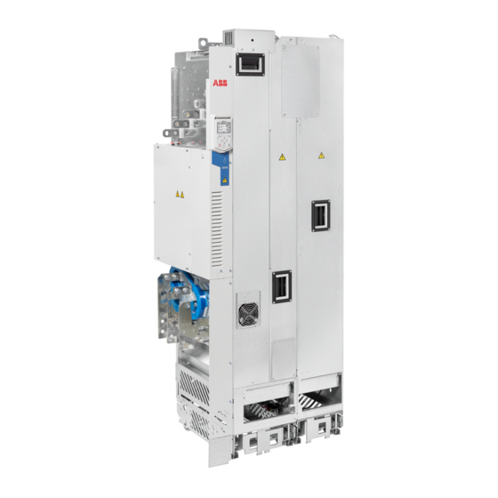
32 Operation principle and hardware description Layout Standard drive module configuration ■ Drive module. Contains line-side converter and Lower front cover motor side converter. LCL filter module Cooling fan cassette LCL filter module connected to the drive module Support legs Circuit board compartment Pedestal Upper front cover... -
Page 33: Drive With Clear Plastic Shrouds (Option +B051)
Operation principle and hardware description 33 Drive with clear plastic shrouds (option +B051) ■ For part descriptions, see section Standard drive module configuration (page 32). For clear plastic shrouds, see section Drive module (page 34) -
Page 34: Drive Module
34 Operation principle and hardware description Drive module ■ +B051 +B051 +H370 Clear plastic shroud to be attached onto the drive Telescopic extraction and insertion ramp module input power cabling (1a). Entry shroud for side cabling (1b) (option +B051). Clear plastic shrouds to be attached onto the drive Control unit module output power cabling (option +B051) Clear plastic shroud to be attached on top of the... -
Page 35: Lcl Filter Module
Operation principle and hardware description 35 Output power cable connection terminals Cover. When removed, you can attach the drive module to the LCL filter module. (assembled at the factory) Grounding terminal for output power cable shields Lifting lugs Metallic shroud. With option +H370, the shroud Connector for charging circuit switch or contactor includes a ground bar. -
Page 36: Control Panel
36 Operation principle and hardware description Control panel ■ In the standard drive module configuration, the control panel is located on the front cover of the module. DPMP-02 door mounting platform allows you to mount the control panel on the cabinet door. For the use of the control panel, see the firmware manual or ACx-AP-x assistant control panels user’s manual (3AUA0000085685 [English]). -
Page 37: Overview Of Power And Control Connections
Operation principle and hardware description 37 Overview of power and control connections The diagram shows the power connections and control interfaces of the drive module. ACQ580-34 Panel port Slot 1 Slot 2 M 3 ~ UDC- UDC+ Line-side converter control unit... -
Page 38: Type Designation Key
38 Operation principle and hardware description Type designation, see section Type designation key Name and address of the manufacturer Frame size Cooling method Degree of protection Ratings, see section Electrical ratings (page 165) Short-circuit withstand strength, see section Electrical power network specification (page 174) Valid markings Serial number. -
Page 39: Option Codes
Operation principle and hardware description 39 Code Description -xxxxA See the ratings table. Voltage range 380…480 V AC. This is indicated in the type designation label as typical input voltage level (3~ 400/480 VAC) Option codes ■ Code Description B051 IP20 shrouds for cabling area E208 Common mode filter (included as standard) - Page 40 40 Operation principle and hardware description Code Description R705 Swedish R707 French R708 Spanish R709 Portuguese R711 Russian R714 Turkish...
-
Page 41: Generic Cabinet Planning Instructions
The installation must always be designed and made according to applicable local laws and regulations. ABB does not assume any liability whatsoever for any installation which breaches the local laws and/or other regulations. Furthermore, if the recommendations given by ABB are not followed, the drive may experience problems that the warranty does not cover. -
Page 42: Grounding Of Mounting Structures
Shrouds ■ The installation of shrouds (touch protection) to fulfill applicable safety regulations is the responsibility of the drive system builder. Ready-made shrouding parts are available from ABB for some cabinet designs, see the ordering information. Tightening torques ■ Unless a tightening torque is specified in the text, the following torques can be used. -
Page 43: Insulation Supports
Generic cabinet planning instructions 43 Insulation supports Size Max. torque Strength class 5 N·m (44 lbf·in) 9 N·m (6.6 lbf·ft) 18 N·m (13.3 lbf·ft) 31 N·m (23 lbf·ft) Cable lugs Size Max. torque Strength class 15 N·m (11 lbf·ft) 32 N·m (23.5 lbf·ft) 50 N·m (37 lbf·ft) Cooling and degrees of protection Planning the cooling... - Page 44 44 Generic cabinet planning instructions Note: Use an extra exhaust fan if the air outlet is on the cabinet door. Air inlet Air outlet Arrange the cooling air flow through the components according to the technical data in the respective hardware manual. See the specifications for: •...
-
Page 45: Preventing The Recirculation Of Hot Air
Generic cabinet planning instructions 45 Preventing the recirculation of hot air Prevent hot air circulation outside the cabinet by leading the outgoing hot air away from the area where the inlet air to the cabinet is taken. Possible solutions are listed below: •... -
Page 46: Liquid-Cooled Drive Systems
46 Generic cabinet planning instructions Liquid-cooled drive systems ■ The cabinet can be sealed from the ambient air. The air inside the cabinet must be able to circulate freely. The power module in the cabinet can have a dedicated fan to push air through an air-to-liquid heat exchanger and the module. - Page 47 • The best galvanic connection between the steel panels is achieved by welding them together as no holes are necessary. If welding is not possible, ABB recommends to leave the seams between the panels unpainted and equipped with special conductive EMC strips to provide adequate galvanic connection.
-
Page 48: Attaching The Cabinet
Entry plate Attaching the cabinet WARNING! Do not attach the cabinet by electric welding. ABB does not assume any liability for damages caused by electric welding as the welding circuit can damage electronic circuits in the cabinet. Cabinet placement on a cable channel Note the following when you plan to place the cabinet on a cable channel: •... -
Page 49: Cubicle Heaters
Attaching the control panel on the cabinet door You can use a mounting platform to attach the control panel on the cabinet door. Mounting platforms for control panels are available as options from ABB. For more information, see Manual Code (English) -
Page 51: Guidelines For Planning The Mechanical Installation
Guidelines for planning the mechanical installation 51 Guidelines for planning the mechanical installation Contents of this chapter This chapter guides in planning drive cabinets and installing the drive module into a user-defined cabinet. The chapter gives cabinet layout examples and free space requirements around the module for cooling. -
Page 52: Layout Example, Door Closed
52 Guidelines for planning the mechanical installation Layout example, door closed This diagram shows a cabinet layout example with the input power cable entry from top and the motor cable entry from bottom. Air inlet for the drive module Operating handle of the disconnector An extra fan is not necessary if an extra air baffle Rubber grommets for degree of protection is used on the cabinet roof (see the following... -
Page 53: Layout Example, Door Open (Standard Drive Module Configuration)
Guidelines for planning the mechanical installation 53 Layout example, door open (standard drive module configuration) L1/U1 L2/V1 L3/W1 T3/W2 T2/V2 T1/U2 A – A B– B Supporting frame of the cabinet Motor cable including the protective ground con- ductor of the drive module Drive module control unit. -
Page 54: Layout Example, Door Open (Option +B051)
54 Guidelines for planning the mechanical installation Note: See also section Required free space (page 58). Layout example, door open (option +B051) L1/U1 L2/V1 L3/W1 T3/W2 T2/V2 T1/U2 A – A B– B Supporting frame of the cabinet LCL filter module Motor cable including the protective ground con- Vertical (2a) and horizontal (2b) air baffles that ductor of the drive module... -
Page 55: Cooling Solutions
Guidelines for planning the mechanical installation 55 Cooling solutions The drawing below shows typical cabinet cooling solutions. The air inlet is at the bottom of the cabinet, while the outlet is on the roof or on the upper part of the door. Use extra exhaust fans if the air outlet is on the cabinet door, see the technical data for the required cooling air flow. -
Page 56: Bookshelf Mounting (Standard Drive Module Configuration)
56 Guidelines for planning the mechanical installation Bookshelf mounting (standard drive module configuration) ■ This diagram shows air baffle positions inside an example cabinet. For the descriptions, see the next page. L1/U1 L2/V1 L3/W1 T3/W2 T2/V2 T1/U2 C – C A - A B - B D –... - Page 57 Guidelines for planning the mechanical installation 57 Air flow to the drive modules, max. 40 °C (104 °F) LCL filter module Vertical air baffle that separates the cool and hot Disconnector and fuses areas in the cabinet Vertical air baffle Contactor Upper horizontal air baffle Drive control unit...
-
Page 58: Bookshelf Mounting (Option +B051)
58 Guidelines for planning the mechanical installation Bookshelf mounting (option +B051) ■ This diagram shows the air baffle position inside an example cabinet. For dimensions of the baffle, see the dimension drawings. L1/U1 L2/V1 L3/W1 T3/W2 T2/V2 T1/U2 B – B C –... -
Page 59: Free Space At The Top Of The Drive Module
The module can be installed in a cabinet with the following dimensions: • width 800 mm (31.50 in) • depth 600 mm (23.62 in) • height 2000 mm (78.74 in). ABB air inlet and outlet kits See chapter Ordering information (page 159). -
Page 61: Mechanical Installation
Mechanical installation 61 Mechanical installation Contents of this chapter This chapter describes alternatives of the mechanical installation of the drive module. It refers to the installation example chapters which contain instructions that depend on the selected drive configuration. Examining the installation site The material below the drive must be non-flammable and strong enough to carry the weight of the drive. -
Page 62: Package Drawings
62 Mechanical installation Package drawings ■ Drive module package 3AXD50000174287_20210204 Transport package contents Finger guard Pedestal guide plate for the LCL filter module Pedestal guide plate for the drive module Accessories box See the box contents on the following pages. Center of gravity symbol Package for LCL filter fan Package for LCL filter pedestal... -
Page 63: Boxes
Mechanical installation 63 Pallet Strap VCI film or bag Drive module with factory installed options and multilingual residual voltage warning sticker, fastening screws in a plastic bag, integrated control unit, control panel and cable or control panel with door mounting kit (option +J410), delivery documents, printed multilingual installation and start- up quick guides. - Page 64 64 Mechanical installation Output connection terminals box with standard drive module configuration Paper fill Output cable connection terminal T3/W2 Output cable connection terminal T2/V2 Output cable connection terminal T1/U2 Grounding terminal Cardboard box Screws and insulators in a plastic bag 3AXD5000009515 Option +H370: input cable connection terminals box...
- Page 65 Mechanical installation 65 Ramp box Cardboard box Combi screws (4 pcs) Ramp extension (50 to 150 mm) Ramp up to 50 mm 3AXD50000476145 Accessories box Screw package Busbar for main contactor - LCL con- nection (3 pcs) Busbar for IGBT - LCL connection (3 pcs) Cardboard box Installation bracket (2 pcs)
-
Page 66: Lcl Filter Module Package
66 Mechanical installation LCL filter module package 3AXD50000113651 VCI bag Plywood support Lid for cardboard sleeve Cardboard sleeve Cardboard support Pallet Strap LCL filter module Examining the delivery Make sure that all items listed in Moving and unpacking (page 61) are present. -
Page 67: Attaching The Drive Module And Lcl Filter Module To A Mounting Plate Or Wall
Mechanical installation 67 Attaching the drive module and LCL filter module to a mounting plate or wall Attach the LCL filter module and the drive module to wall or a mounting plate at the points shown below. You can attach the modules to Rittal VX25 enclosure with the mounting brackets delivered with the drive, see Step-by-step drawings for an installation example of standard drive configuration in Rittal VX25 800 mm wide enclosure (page... -
Page 68: Grounding The Drive Module And The Lcl Filter Module
68 Mechanical installation Grounding the drive module and the LCL filter module Ground the drive module and the LCL filter module from the fastening points: Installing the drive in Rittal VX25 enclosure For an installation example on how to install the drive module into a Rittal VX25 enclosure, Installation example in Rittal VX25 enclosure (page 133) Step-by-step drawings for an installation example of standard drive configuration in Rittal VX25 800 mm wide... -
Page 69: Optional Input Power Cable Connection Terminals And Ground Busbar Assembly (+H370)
Mechanical installation 69 Optional input power cable connection terminals and ground busbar assembly (+H370) Install the metallic shroud with ground bar as shown below. Combi screw M4×8 Torx T20 2 N·m Connect the input power cable connection terminals as shown in Step-by-step drawings for an installation example of standard drive configuration in Rittal VX25 800 mm wide enclosure (page... -
Page 71: Guidelines For Planning The Electrical Installation
The installation must always be designed and made according to applicable local laws and regulations. ABB does not assume any liability whatsoever for any installation which breaches the local laws and/or other regulations. Furthermore, if the recommendations given by ABB are not followed, the drive may experience problems that the warranty does not cover. -
Page 72: North America
Examining the compatibility of the motor and drive Use asynchronous AC induction motors, permanent magnet synchronous motors, AC induction servomotors or ABB synchronous reluctance motors (SynRM motors) with the drive. Select the motor size and drive type from the rating table on basis of the AC line voltage and motor load. -
Page 73: Requirements Table
Guidelines for planning the electrical installation 73 time. The pulse voltage can almost double at the motor terminals, depending on the attenuation and reflection properties of the motor cable and the terminals. This can cause additional stress on the motor and motor cable insulation. Modern variable speed drives with their fast rising voltage pulses and high switching frequencies can generate current pulses that flow through the motor bearings. - Page 74 74 Guidelines for planning the electrical installation This table shows the requirements when an ABB motor is in use. Motor type Nominal AC line Requirement for voltage Motor insula- ABB du/dt and common mode filters, insulated tion system N-end motor bearings <...
- Page 75 Guidelines for planning the electrical installation 75 This table shows the requirements when a non-ABB motor is in use. Motor type Nominal AC line Requirement for voltage Motor insula- ABB du/dt and common mode filters, insulated tion system N-end motor bearings <...
-
Page 76: Availability Of Du/Dt Filter And Common Mode Filter By Drive Type
The rated output power of high-output motors is higher than what is stated for the particular frame size in EN 50347 (2001). If you plan to use a non-ABB high-output motor or an IP23 motor, consider these additional requirements for protecting the motor insulation and bearings in drive systems: •... -
Page 77: Additional Data For Calculating The Rise Time And The Peak Line-To-Line Voltage
Guidelines for planning the electrical installation 77 Nominal AC supply Requirement for voltage Motor insulation system ABB du/dt and common mode filters, insulated N- end motor bearings < 100 kW or frame size 100 kW < P < 350 kW or <... -
Page 78: Selecting The Power Cables
78 Guidelines for planning the electrical installation Û du/dt -------------(1/ µs) Û -- - - -- - - - - - (1/ µs) l (m) l (m) Drive with du/dt filter Drive without du/dt filter Motor cable length Û Relative peak line-to-line voltage (du/dt)/U Relative du/dt value Note: Û... -
Page 79: Typical Power Cable Sizes
Guidelines for planning the electrical installation 79 Unless local wiring regulations state otherwise, the cross-sectional area of the protective conductor must agree with the conditions that require automatic disconnection of the supply required in 411.3.2 of IEC 60364-4-41:2005 and be capable of withstanding the prospective fault current during the disconnection time of the protective device. -
Page 80: Alternate Power Cable Types
80 Guidelines for planning the electrical installation Cable type Use as input power cabling Use as motor cabling Symmetrical shielded (or armored) cable with three phase conductors and symmetrically constructed PE conductor and a shield (or armor) Symmetrical shielded (or armored) cable with three phase conductors and a shield (or armor), and separ- ate PE conductor/cable... -
Page 81: Not Allowed Power Cable Types
Additional guidelines, North America ■ ABB recommends the use of conduit for power wiring to the drive and between the drive and the motor(s). Due to the variety of application needs, metallic and non-metallic conduit can be used. ABB recommends the use of metallic conduit. -
Page 82: Metal Conduit
82 Guidelines for planning the electrical installation Wiring method Notes 1) 2) Conduit - Metallic Electrical metallic tubing: Type EMT Prefer symmetrical shielded VFD cable. Use separate conduit run for each motor. Rigid metal conduit: Type RMC Do not run input power wiring and motor wiring in the Liquid-tight flexible metal electrical conduit: Type LFMC same conduit. -
Page 83: Selecting The Control Cables
Relay cable ■ The cable type with braided metallic shield (for example ÖLFLEX by LAPPKABEL, Germany) has been tested and approved by ABB. Control panel to drive cable ■ Use EIA-485 with male RJ-45 connector, cable type Cat 5e or better. The maximum permitted... -
Page 84: Pc Tool Cable
84 Guidelines for planning the electrical installation PC tool cable ■ Connect the Drive composer PC tool to the drive through the USB port of the control panel. Use a USB Type A (PC) - Type Mini-B (control panel) cable. The maximum length of the cable is 3 m (9.8 ft). -
Page 85: General Guidelines - North America
Guidelines for planning the electrical installation 85 General guidelines – North America ■ Make sure that the installation is in accordance with national and local codes. Obey these general guidelines: • Use separate conduits for the input power, motor, brake resistor (optional), and control cabling. -
Page 86: Separate Control Cable Ducts
86 Guidelines for planning the electrical installation Separate control cable ducts ■ Put 24 V DC and 230 V AC (120 V AC) control cables in separate ducts, unless the 24 V DC cable is insulated for 230 V AC (120 V AC) or insulated with an insulation sleeving for 230 V AC (120 V AC). -
Page 87: Protecting The Motor Against Overload Without Thermal Model Or Temperature Sensors
Guidelines for planning the electrical installation 87 The most common temperature sensor types are PTC or Pt100. For more information, see the firmware manual. Protecting the motor against overload without thermal model or ■ temperature sensors Motor overload protection protects the motor against overload without using motor thermal model or temperature sensors. -
Page 88: Protecting The Input Power Cable Against Thermal Overload
88 Guidelines for planning the electrical installation Protecting the input power cable against thermal overload The drive has overload protection as standard. If the sizing of the input power cable is correct, the drive overload protection protects also the cable against overload. In case of parallel input power cables, it may be necessary to protect each cable separately. -
Page 89: Protecting The Drive Against Ground Faults
Guidelines for planning the electrical installation 89 • option module types that you can use for the motor temperature sensor connection • insulation or isolation level that each option module forms between its temperature sensor connector and other connectors • temperature sensor types that you can connect to each option module •... -
Page 90: Implementing The Undervoltage Control (Power-Loss Ride-Through)
Power-loss ride-through function. Implementing the functions provided by the FSO-xx safety functions module You can order a safety function module from ABB. The cabinet builder can use the module for implementing various safety functions. Using power factor compensation capacitors with the drive Power factor compensation is not needed with AC drives. -
Page 91: Implementing An Atex-Certified Motor Thermal Protection
Guidelines for planning the electrical installation 91 Implementing an ATEX-certified motor thermal protection With option +Q971, the drive provides ATEX-certified safe motor disconnection without contactor using the drive Safe torque off function. To implement the thermal protection of a motor in explosive atmosphere (Ex motor), you must also: •... -
Page 92: Example Bypass Connection
92 Guidelines for planning the electrical installation WARNING! Never connect the drive output to the electrical power network. The connection may damage the drive. Example bypass connection ■ An example bypass connection is shown below. Drive main switch Bypass circuit breaker Drive main contactor Bypass contactor Drive output contactor... -
Page 93: Switching The Motor Power Supply From Direct-On-Line To Drive
Guidelines for planning the electrical installation 93 4. Wait for 10 seconds to allow the motor magnetization to dissipate. 5. Start the motor with S41. Switching the motor power supply from direct-on-line to drive 1. Stop the motor with S42. 2. -
Page 95: Electrical Installation
Electrical installation 95 Electrical installation Contents of this chapter This chapter gives instructions on the wiring of the drive. Safety WARNING! If you are not a qualified electrical professional, do not do installation or maintenance work. Obey the safety instructions of the drive. If you ignore them, injury or death, or damage to the equipment can occur. -
Page 96: Measuring The Insulation
Use a measuring voltage of 1000 V DC. The insulation resistance of an ABB motor must be more than 100 Mohm (reference value at 25 C [77°F]). For the insulation resistance of other motors, refer to the manufacturer’s instructions. -
Page 97: Corner-Grounded And Midpoint-Grounded Delta Systems
Electrical installation 97 Corner-grounded and midpoint-grounded delta systems ■ WARNING! Do not install the drive on a corner-grounded or midpoint-grounded delta system. Disconnecting the EMC filter and ground-to-phase varistor does not prevent damage to the drive. Identifying the grounding system of the electrical power network ■... -
Page 98: When To Disconnect Emc Filter And Ground-To-Phase Varistor: Tn-S, It, Corner-Grounded Delta, And Midpoint-Grounded Delta Systems
98 Electrical installation When to disconnect EMC filter and ground-to-phase varistor: TN-S, ■ IT, corner-grounded delta, and midpoint-grounded delta systems Symmetrically grounded TN systems (TN-S systems) Do not disconnect EMC AC and VAR wires. Corner-grounded delta systems Do not install the drive on a corner-grounded system. Midpoint-grounded delta systems Do not install the drive on a midpoint grounded system. -
Page 99: Disconnecting Instructions
• Because the varistor wire has been disconnected, ABB does not guarantee the EMC category. • ABB does not guarantee the functioning of the ground leakage detector built inside the drive. • In large systems the residual current device can trip without a real reason. -
Page 100: Power Cable Connection Diagram
50% of the conductivity of the phase conductor, use a separate PE cable (2a) or a cable with a grounding conductor (2b) ABB recommends 360-degree grounding at the cabinet entry if a shielded cable is used. Ground the other end of the input cable shield or PE conductor at the distribution board. - Page 101 Electrical installation 101 Use a separate grounding cable if the conductivity of the cable shield is < 50% of the conductivity of the phase conductor and there is no symmetrically constructed grounding conductor in the cable (see Guidelines for planning the electrical installation (page 71) Common mode filter du/dt filter (option) EMC filter...
-
Page 102: Preparing The Cable Ends And Making 360-Degree Grounding At The Cable Entry
102 Electrical installation Preparing the cable ends and making 360-degree grounding at the ■ cable entry 1. Peel off 3…5 cm (1 1/4 … 2 in) of the outer insulation of the cables at the cable entries with the conductive sleeves for the 360° high-frequency grounding. 2. -
Page 103: Power Cable Connection Procedure
Electrical installation 103 5. Remove rubber grommets from the entry plate for the cables to be connected. Cut adequate holes into the rubber grommets. Slide the grommets onto the cables. Slide the cables through the entry plate and attach the grommets to the holes. 6. -
Page 104: Connecting The Control Cables To The Integrated Control Unit
104 Electrical installation 6. Twist the cable shields of the input cables into bundles and connect them and any separate ground conductors or cables to the drive module ground terminal or to the cabinet PE busbar. 7. Connect the phase conductors of the input cables to terminals L1/U1, L2/V1 and L3/W1 of the drive module. -
Page 105: Connecting External Power Supply Wires To The Control Units
Electrical installation 105 5. Ground the shields of the control cables at the clamp plate. The shields should be continuous as close to the terminals of the control unit as possible. Only remove the outer jacket of the cable at the cable clamp so that the clamp presses on the bare shield. The shield (especially in case of multiple shields) can also be terminated with a lug and fastened with a screw at the clamp plate. -
Page 106: Connecting A Control Panel
106 Electrical installation ISU ZCU XPOW for ext. +24VDC Connecting a control panel With control panel door mounting platform, connect the control panel as follows: 1. Connect an Ethernet cable to the RJ-45 connector of the control panel. 2. Connect the other end of the cable to the panel port (X12) of the control unit. Note: When a PC is connected to the control panel, the control panel keypad is disabled. -
Page 107: Connecting A Pc
Electrical installation 107 Connecting a PC WARNING! Do not connect the PC directly to the control panel connector of the control unit as this can cause damage. A PC (with eg, the Drive composer PC tool) can be connected as follows: 1. -
Page 108: Option Slot 2 (I/O Extension Modules)
108 Electrical installation Option slot 2 (I/O extension modules) ■ 1. Put the module carefully into its position on the control unit. 2. Tighten the mounting screw. 3. Tighten the grounding screw (CHASSIS) to 0.8 N·m (7 lbf·in). The screw grounds the module. -
Page 109: Option Slot 1 (Fieldbus Adapter Modules)
Electrical installation 109 Option slot 1 (fieldbus adapter modules) ■ 1. Put the module carefully into its position on the control unit. 2. Tighten the mounting screw (CHASSIS) to 0.8 N·m (7 lbf·in). The screw tightens the connections and grounds the module. It is necessary for fulfilling the EMC requirements and for correct operation of the module. -
Page 111: Control Unit
Control unit 111 Control unit Contents of this chapter This chapter contains the default I/O connection diagram, descriptions of the terminals and technical data for the drive control unit (CCU-24). -
Page 112: Layout
112 Control unit Layout The layout of the external control connection terminals on the drive module control unit is shown below. SLOT 1 SLOT 1 Option slot 1 (fieldbus adapter modules) ANALOG IN/OUT 1…3 Analog input 1 4…6 Analog input 2 1…3 7…9 Analog outputs... -
Page 113: Default I/O Connection Diagram
Control unit 113 Default I/O connection diagram The default control connections for the Water default are shown below. Reference voltage and analog inputs and outputs Signal cable shield (screen) Output frequency/speed reference: 0…10 V 1…10 kohm AGND Analog input circuit common +10V Reference voltage 10 V DC Actual feedback: 0…10 V... -
Page 114: Switches
114 Control unit Current [0(4)…20 mA, R = 100 ohm] or voltage [0(2)…10 V, R >200 kohm]. Change of setting requires changing the corresponding parameter. Total load capacity of the Auxiliary voltage output +24V (X2:10) is 6.0 W (250 mA / 24 V) minus the power taken by the option modules installed on the board. -
Page 115: Npn Configuration For Digital Inputs (X2 & X3)
Control unit 115 Internal +24 V power supply External +24 V power supply PNP connection (source) PNP connection (source) X2 & X3 X2 & X3 +24V +24V 0 V DC DGND DGND +24 V DC DCOM DCOM WARNING! Do not connect the +24 V AC cable to the control board ground when the control board is powered using an external 24 V AC supply. -
Page 116: Connection Examples Of Two-Wire And Three-Wire Sensors To Analog Input (Ai2)
116 Control unit Connection examples of two-wire and three-wire sensors to analog ■ input (AI2) Note: The maximum capability of the auxiliary voltage output (24 V DC [250 mA]) must not be exceeded. An example of a two-wire sensor/transmitter supplied by the drive auxiliary voltage output is shown below. -
Page 117: Safe Torque Off (X4)
Control unit 117 AGND AGND One, two or three Pt100 sensors; one, two or three Pt1000 sensors; or one Ni1000, KTY83 or KTY84 sensor Set the input type to voltage for analog input AI1 or analog input AI2 with parameters. Set the appropriate analog input unit to V (volt) in parameter group 12 Standard AI. -
Page 118: Technical Data
118 Control unit Technical data External power supply Maximum power: 36 W, 1.50 A at 24 V AC/DC ±10% as standard Term. 40, 41 Terminal size: 0.14…2.5 mm +24 V DC output Total load capacity of this outputs is 6.0 W (250 mA / 24 V) minus the power taken by the option modules installed on board. - Page 119 Control unit 119 Safe torque off (STO) inputs IN1 24 V DC logic levels: "0" < 5 V, "1" > 13 V and IN2 (Term. 37 and 38) : 2.47 kohm Terminal size: 0.14…2.5 mm Embedded fieldbus (X5) Connector pitch 5 mm, wire size 2.5 mm Physical layer: EIA-485 Cable type: Shielded twisted pair cable with twisted pair for data and a wire or pair for signal ground, nominal impedance 100…165 ohms, for example...
- Page 120 120 Control unit Isolation areas SLOT 1 1…3 4…6 7…8 10…12 24 V 13…15 16…18 34…38 EIA/R5-485 40, 41 Ext. 24 V SLOT 2 19…21 22…24 25…27 Panel port Power unit connection at the bottom of the control unit Reinforced insulation (IEC/EN 61800-5-1:2007, UL 61800- 5-1 First edition) Functional insulation (IEC/EN 61800-5-1:2007, UL 61800- 5-1 First edition)
- Page 121 Control unit 121 Ground isolation diagram Slot 1 Slot 2 AGND +10V AGND AGND X2 & X3 +24V DGND DCOM X6, X7, X8 RO1C RO1A RO1B RO2C RO2A RO2B RO3C RO3A RO3B DGND OUT1 OUT2 SGND 24VAC/DC+in 24VAC/DC-in Jumper installed at factory...
-
Page 123: External Control Unit (Option +P906)
External control unit (option +P906) 123 External control unit (option +P906) Contents of this chapter This chapter describes the external control unit option +P906 and it's installation. The dimension drawing is included. Product overview Option +P906 allows the drive control unit CCU-24 to be installed separately from the main drive module, for instance in a separate compartment. -
Page 124: Layout
124 External control unit (option +P906) Layout ■ Attaching points Duct for cables from drive module to be connec- ted to the ZBIB board at the back of the control unit. Connectors. For descriptions, see chapter Control unit (page 111). Cables for connecting the external control unit to the drive module: Cables... -
Page 125: Unpacking The Delivery
External control unit (option +P906) 125 ZBIB INU STO X7 (STO1) BGDR X8 (STO2) 2560 mm (8.4 ft) QOIA ZINT 3 m (10 ft) ZPOW CAT 5e 3 m (9.8 ft) DPMP-03 CCU-24 control unit Drive module 2 × Safe Torque Off (STO) cables 1 ×... -
Page 126: Installation Procedure
126 External control unit (option +P906) Installation procedure ■ Optical components WARNING! Obey these instructions. If you ignore them, damage to the equipment can occur. • Handle the fiber optic cables with care. • When you unplug the fiber optic cables, always hold the connector, not the cable itself. •... - Page 127 External control unit (option +P906) 127 4. Connect the cables to their connectors on the ZBIB board. View of ZBIB ZBIB connectors Cables from QOIA X7 (STO 1) INU STO X8 (STO 2) INU STO X7 X8 STO1STO2 V20V21 V1 V2 5.
- Page 128 128 External control unit (option +P906) 6. The kit includes a plate for the customer cable screens. Attach the small bracket (a) first, then the full clamp plate (b). 7. Mark and drill the required holes in the mounting plate for attaching the control unit. Be careful to control the swarf from the drill.
- Page 129 External control unit (option +P906) 129 8. Lift the control unit onto the mounting screws. Tighten the screws. 9. Attach the optional modules. 10. Ground the shields of the control cables at the clamp plate. The shields should be continuous as close to the terminals of the control unit as possible. Only remove the outer jacket of the cable at the cable clamp so that the clamp presses on the bare shield.
-
Page 130: Connecting The Control Unit To The Drive Module
130 External control unit (option +P906) Connecting the control unit to the drive module ■ 1. Remove the middle front cover of the the drive module. A view of drive module with optional clear plastic shrouds is shown below. 2. Remove the cover plate from the control cable entry and put the rubber grommet in its place. -
Page 131: Maintenance
External control unit (option +P906) 131 3. Connect the control cables to the drive module . Make sure that that cables are not against sharp edges or bare live parts Drive module ZBIB INU STO ISU ext. 24VDC panel INU STO X7 (STO1) QOIA ZBIB... -
Page 132: Dimension Drawing
132 External control unit (option +P906) Dimension drawing... -
Page 133: Installation Example In Rittal Vx25 Enclosure 133
In this chapter, the drive module is installed in a 800 mm wide Rittal VX25 enclosure in a bookshelf way of mounting. The module is placed in an upright position on the cabinet bottom with its front facing the cabinet door. Available alternative ABB parts are also given. For control cable installation, see chapter Electrical installation (page 95). -
Page 134: Required Parts
8806.000 Enclosure without bottom plates and side panels. Includes supports for installing air baffles. 7967.000 Spacers for roof plates / ABB roof (one set = four pieces) 8100.743 Punched section with mounting flange, inner mounting level for 800 mm horizontal Contact ABB for the suitable filter Air filter. -
Page 135: Installing The Drive Module And Lcl Filter Module Into An Enclosure
Installation example in Rittal VX25 enclosure 135 Step Task For instructions, see Connect the power cables and clear plastic Connecting the motor cables and installing the shrouds to the drive module. shrouds (option +B051) (page 136) Connect the power supply cable to the LCL filter Connecting the input cables and installing the cooling fan. -
Page 136: Connecting The Motor Cables And Installing The Shrouds (Option +B051)
136 Installation example in Rittal VX25 enclosure Unfasten the extraction/installation ramp and attach the LCL filter module to bottom plate. Drive module Attach the extraction/installation ramp to the drive module pedestal guide plate. Remove the sheeting from the clear plastic shrouds (option +B051) of the drive module from both sides. -
Page 137: Connecting The Input Cables And Installing The Shrouds (Option +B051)
Installation example in Rittal VX25 enclosure 137 Remove the plastic sheeting from the motor cable clear plastic shroud (option +B051) from both sides. Install the shroud (option +B051) on the motor cable connections, Install the lower front cover to the drive module. Drill holes for the power cables to the bottom clear plastic shrouds. -
Page 138: Installing The Roof And Door (Rittal Parts)
VX25 800 mm wide enclosure (page 229) • Air baffles (page 189) Installing the roof and door (Rittal parts) This drawing shows a layout tested by ABB. Door Install these gratings as close to each other as possible. Remove the filter mats. -
Page 139: Removing The Protective Covering From The Drive Module And Lcl Filter Module Air Outlet
Installation example in Rittal VX25 enclosure 139 Removing the protective covering from the drive module and LCL filter module air outlet WARNING! Remove the protective covering from the top of the drive module after the installation. If the covering is not removed, the cooling air cannot flow freely through the module and the drive will run to overtemperature. -
Page 141: Installation Checklist
Installation checklist 141 Installation checklist Contents of this chapter This chapter contains a checklist of the mechanical and electrical installation of the drive. Checklist Examine the mechanical and electrical installation of the drive before start-up. Go through the checklist together with another person. WARNING! Obey the safety instructions of the drive. - Page 142 142 Installation checklist Make sure that … The cooling air flows freely in and out of the drive. Air recirculation inside the cabinet is not possible (air baffle plates are on place, or there is another air guiding solution). If the drive is connected to a network other than a symmetrically grounded TN-S system: You have done all the required modifications (for example, you may need to disconnect the EMC filter or ground- to-phase varistor).
-
Page 143: Start-Up
Start-up 143 Start-up Contents of this chapter This chapter describes the start-up procedure of the drive. Start-up procedure 1. Only qualified electrical professionals are allowed to start-up the drive. 2. Make sure that the installation of the drive module has been checked according to the checklist in chapter Installation checklist, and that the motor and driven equipment are ready for start. -
Page 145: Fault Tracing
Fault tracing 145 Fault tracing Contents of this chapter This chapter describes the fault tracing possibilities of the drive. LEDs Drive LEDs ■ There is a green POWER and a red FAULT LED visible when the control panel is removed. If a control panel is attached to the drive, switch to remote control (otherwise a fault will be generated), and then remove the panel to be able to see the LEDs. -
Page 146: Control Panel Leds
146 Fault tracing The table below describes the drive LED indications. POWER FAULT LEDs off LED lit and steady LED blinking No power Green Power supply of the unit is on Green Blinking: (POWER) (POWER) Drive in an alarm state Blinking for one second: Drive selected on the control panel when multiple drives are connected to... -
Page 147: Maintenance
For more information, consult your local ABB Service representative (www.abb.com/searchchannels). The maintenance and component replacement intervals are based on the assumption that the equipment is operated within the specified ratings and ambient conditions. ABB recommends annual drive inspections to ensure the highest reliability and optimum performance. -
Page 148: Recommended Maintenance Intervals After Start-Up
148 Maintenance Recommended annual actions by the user Annually Connections and environment Quality of supply voltage Spare parts Spare parts DC circuit capacitors reforming, spare modules and spare capacitors Inspections by the user Tightness of terminals Dustiness, corrosion and temperature Heat sink cleaning Recommended maintenance intervals after start-up ■... -
Page 149: Cleaning The Interior Of The Heatsink
Maintenance 149 1. Stop the drive and do the steps in section Electrical safety precautions (page 18) before you start the work. 2. Open the cabinet door. 3. Clean the interior of the cabinet. Use a vacuum cleaner and a soft brush. 4. -
Page 150: Cleaning The Interior Of The Lcl Filter
Reset the running time signal after fan replacement. Replacement fans are available from ABB. Do not use other than ABB specified spare parts. Replacing the auxiliary cooling fans of the drive module ■... -
Page 151: Replacing The Drive Module Main Cooling Fans
Maintenance 151 Fan at the bottom of the circuit board compartment: 1. Stop the drive and do the steps in section Electrical safety precautions (page 18) before you start the work. 2. Undo the mounting screw of the fan cassette. 3. -
Page 152: Replacing The Lcl Filter Module Cooling Fan
152 Maintenance 3. Undo the mounting screws of the fan cassette. 4. Pull the fan cassette out. 5. Undo the mounting screws of the fan(s). 6. Install the new fans in reverse order. 7. Reset the counter (if used) in group 5 in the primary control program. Replacing the LCL filter module cooling fan ■... -
Page 153: Replacing The Standard Drive Module
Maintenance 153 Replacing the standard drive module WARNING! Obey the safety instructions of the drive. If you ignore them, injury or death, or damage to the equipment can occur. Handle the drive module carefully: • Use safety shoes with a metal toe cap to prevent foot injury. •... - Page 154 154 Maintenance 3AUA0000086323 1. Stop the drive and do the steps in section Electrical safety precautions (page 18) before you start the work. 2. Remove the clear plastic shrouds on the power cables and parts in front of the drive module (if present).
- Page 155 Maintenance 155 10. Adjust the extraction/installation ramp to the correct height and attach it to the cabinet base with the two mounting screws.
-
Page 156: Replacing The Lcl Filter Module
156 Maintenance 11. Pull the drive module carefully out of the cabinet preferably with help from another person. 12. Install the new module in reverse order. Replacing the LCL filter module Replace the LCL filter module in the same way as the drive module. -
Page 157: Capacitors
Capacitor failure is usually followed by damage to the unit and an input cable fuse failure, or a fault trip. If you think that any capacitors in the drive have failed, contact ABB. Reforming the capacitors ■... -
Page 158: Functional Safety Components
Note that some of the components may already have been renewed earlier, restarting their mission time. The remaining mission time of the whole circuit is however determined by its oldest component. Contact your local ABB service representative for more information. -
Page 159: Ordering Information
This chapter gives ordering information on additional components available from ABB for the drive module installation. Note: This chapter only lists the installation accessories available from ABB. All other parts must be sourced from a third party by the system integrator. -
Page 160: Output (Du/Dt) Filters
160 Ordering information Type Description Ordering code Illustration Door mounting kit for flush mounting. Includes a control DPMP-01 panel mounting platform, an IP54 3AUA0000108878 cover and a 3- meter panel con- nection cable. Output (du/dt) filters See section du/dt filters. Cabinet ventilation Air inlet kits ■... - Page 161 Ordering information 161 Enclosure width / Kit code Ordering code Illustration Degree of protection 800 mm / IP42 A-8-X-026 3AUA0000117009 Instruction code: 3AUA0000116875 800 mm / IP54 A-8-X-029 3AXD50000009186 Instruction code: 3AXD50000010001...
-
Page 162: Air Outlet Kits
162 Ordering information Air outlet kits ■ Enclosure width / Kit code Ordering code Illustration Degree of protection 800 mm / IP20 A-4-X-062 3AUA0000125201 Instruction code: 3AXD50000001982 Note: Fan to be ordered separately 800 mm / IP42 A-4-X-060 3AUA0000114967 Instruction code: 3AUA0000115290 Note: Fan to be ordered separately 800 mm / IP54 (IEC) A-4-X-064... -
Page 163: Cooling Fans
Ordering information 163 Enclosure width / Kit code Ordering code Illustration Degree of protection 800 mm / IP54 (UL) A-4-X-067 3AXD50000010362 Instruction code: 3AXD50000010284 Note: Fan to be ordered separately Cooling fans Two cooling fans must be installed inside the air outlet compartment to ensure sufficient cooling of the cabinet. -
Page 165: Technical Data
Technical data 165 Technical data Contents of this chapter This chapter contains the technical specifications of the drive, for example, the ratings, sizes and technical requirements, provisions for fulfilling the requirements for CE and other markings. Electrical ratings The nominal rating for the drive modules with 50 Hz and 60 Hz supply are given below. IEC RATINGS Drive Frame... - Page 166 166 Technical data IEC RATINGS Drive Frame Input Max cur- Output ratings type size rating rent Nominal ratings Light-duty use Heavy-duty use ACQ580- 34-… 650A-4 IEC RATINGS Drive Frame Input Max. Output ratings type size rating current Nominal ratings Light-duty use Heavy-duty use ACQ580- = 480 V...
-
Page 167: When Is Derating Necessary
The power ratings apply to most IEC 34 motors at the nominal voltage of the drive. ABB recommends to select the drive, motor and gear combination for the required motion profile with the DriveSize dimensioning tool available from ABB. - Page 168 168 Technical data 4000 m 13123 ft 0.80 3500 m 11429 ft 0.85 3000 m 0.90 9842 ft 0.95 2500 m 8202 ft 1.00 2000 m 6562 ft 1500 m 4921 ft 1000 m 3300 ft +20 °C +25 °C +30 °C +35 °C +40 °C...
-
Page 169: Fuses (Iec)
Cooper Bussmann for protection against short-circuit in the input power cable of drive are listed below. Ultrarapid (aR) fuses Input Fuse Drive type current ACQ580-34- Type DIN 43653 Size = 400 V, IEC 246A-4 74000 170M5408 293A-4... -
Page 170: Fuses (Ul)
UL 248-13 Recognized fuses for branch circuit protection per NEC are listed below. Obey local regulations. Ultrarapid (aR, semiconductor) fuses Drive type Input cur- Type Flush Type DIN Type French rent (A) ACQ580-34- Type US Style 43653 Style = 480 V 240A-4 170M5408 170M5008 170M5608... -
Page 171: Dimensions, Weights And Free Space Requirements
Technical data 171 Dimensions, weights and free space requirements Standard drive module configuration (drive module + LCL filter module) Frame Height Width Depth Weight size 1722 67.8 25.1 19.9 Weight of the drive module: 185 kg (409 lb) Weight of the LCL filter module: 180 kg (396 lb) Drive module + LCL filter module with options +B051 and +H370 Frame Height... -
Page 172: Losses, Cooling Data And Noise
This table shows typical heat loss values, required air flow and noise at the nominal ratings of the drive. The heat loss values can vary depending on voltage, cable conditions, motor efficiency and power factor. To obtain more accurate values for given conditions, use ABB DriveSize tool (http://new.abb.com/drives/software-tools/drivesize). -
Page 173: Power Cables
PE conductor. See also section Terminal and entry data for the power cables (page 172). Drive type UL (NEC) ACQ580-34- Cu cable type Al cable type Cu cable type AWG/kcmil = 400 V, 480 V (IEC) 246A-4 2 ×... -
Page 174: Electrical Power Network Specification
174 Technical data Electrical power network specification Voltage (U ACQ580-34-xxxx-4 drive modules: 380…480 V AC 3-phase +10%…-15%. This is indicated in the type designation label as typical input voltage levels 3~400/480 V AC. Network type TN (grounded) and IT (ungrounded) systems... -
Page 175: Motor Connection Data
Asynchronous AC induction motors, permanent magnet motors and ABB synchron- ous reluctance motors (SynRM motors) Voltage (U 0 to U nominal, can be boosted higher but requires derating. Contact ABB for more information. Frequency (f 0…500 Hz Note: Operation above 150 Hz can require type-specific derating. For more inform- ation, contact your local ABB representative. -
Page 176: Control Panel Type
Longer motor cables cause a motor voltage decrease which limits the available motor power. The decrease depends on the motor cable length and characteristics. Contact ABB for more information. Note that a sine filter (optional) at the drive output also causes a voltage decrease. -
Page 177: Materials
Technical data 177 Relative humidity 5…95% Max. 95% Max. 95% No condensation allowed. Maximum allowed relative humidity is 60% in the pres- ence of corrosive gases. Contamination IEC/EN 60721-3-3:2002 IEC 60721-3-1:1997 IEC 60721-3-2:1997 Chemical gases Class 3C2 Class 1C2 Class 2C2 Solid particles Class 3S2. -
Page 178: Applicable Standards
IEC 62635 guidelines. To aid recycling, plastic parts are marked with an appropriate identification code. Contact your local ABB distributor for further information on environmental aspects and recycling instructions for professional recyclers. End of life treatment must follow international and local regulations. -
Page 179: Emc Compliance (Iec/En 61800-3:2004)
Technical data 179 EAC (Eurasian Conformity) mark Product complies with the technical regulations of the Eurasian Customs Union. EAC mark is required in Russia, Belarus and Kazakhstan. Electronic Information Products (EIP) green mark The product complies with the People’s Republic of China Electronic Industry Standard (SJ/T 11364- 2014). -
Page 180: Category C4
180 Technical data 1. The drive is equipped with internal EMC filter (+E210). 2. The motor and control cables are selected as specified in the hardware manual. 3. The drive is installed according to the instructions given in the hardware manual. 4. -
Page 181: Ul And Csa Checklist
Technical data 181 UL and CSA checklist WARNING! Operation of this drive requires detailed installation and operation instructions provided in the hardware and software manuals. The manuals are provided in electronic format in the drive package or on the Internet. Keep the manuals with the drive at all times. -
Page 182: Disclaimer
ABB and its affiliates are not liable for damages and/or losses related to such security breaches, any unauthorized... -
Page 183: Dimension Drawings
Dimension drawings 183 Dimension drawings Contents of this chapter This chapter contains dimension drawings of the drive modules with optional parts for Rittal VX25 cabinet assembly. -
Page 184: Standard Configuration (+E208 And +E210 Included)
184 Dimension drawings Standard configuration (+E208 and +E210 included) -
Page 185: Drive Module With Option +B051
Dimension drawings 185 Drive module with option +B051... -
Page 186: Drive Module With Options +B051, +H370
186 Dimension drawings Drive module with options +B051, +H370... -
Page 187: Lcl Filter Module
Dimension drawings 187 LCL filter module... -
Page 188: Bottom Plate
188 Dimension drawings Bottom plate This drawing shows the dimensions of the bottom plate for 800 mm Rittal VX25 enclosure. It is not an ABB product. -
Page 189: Air Baffles
Dimension drawings 189 Air baffles This drawing shows the dimensions of the air baffles around the drive module with option +B051 for 800 mm Rittal VX25 enclosure. These are not ABB products. LEFT RIGHT REAR FRONT 3AXD50000453931 Material of the air baffles ■... -
Page 191: Example Circuit Diagrams
Example circuit diagrams 191 Example circuit diagrams Contents of this chapter This chapter shows an example circuit diagram for a cabinet-installed drive module. Example circuit diagram This diagram is an example for the main wiring of a drive cabinet. Note that the diagram includes components which are not included in a basic delivery (* plus code options, ** other options, *** to be acquired by the customer). - Page 192 192 Example circuit diagrams Cabinet *ACx-AP-x control panel CCU control unit ***Main contactor **Motor temperature supervision ***Switch fuse disconnector Common mode filter **du/dt filter or sine filter Drive module Input and output signals Alarm Supply 360 degree grounding recommended...
-
Page 193: The Safe Torque Off Function
The Safe torque off function 193 The Safe torque off function Contents of this chapter This chapter describes the Safe torque off (STO) function of the drive and gives instructions for its use. Description The Safe torque off function can be used, for example, as the final actuator device of safety circuits that stop the drive in case of danger (such as an emergency stop circuit). -
Page 194: Compliance With The European Machinery Directive
194 The Safe torque off function Standard Name IEC 61326-3-1:2017 Electrical equipment for measurement, control and laboratory use – EMC requirements – Part 3-1: Immunity requirements for safety-related systems and for equipment intended to perform safety-related functions (functional safety) – General industrial applications IEC 61508-1:2010 Functional safety of electrical/electronic/programmable electronic safety- related systems –... -
Page 195: Wiring
The Safe torque off function 195 Wiring For the electrical specifications of the STO connection, see the technical data of the control unit. Connection principle ■ Single ACQ580-34 drive, internal power supply OUT1 + 24 V DC OUT2 + 24 V DC SGND... -
Page 196: Wiring Examples
196 The Safe torque off function Drive Control unit Control logic To motor Activation switch Wiring examples ■ Single ACQ580-34 drive, internal power supply OUT1 OUT2 SGND Drive Safety PLC Safety relay Single ACQ580-34 drive, external power supply 24 V DC... -
Page 197: Multiple Acq580-34 Drives, Internal Power Supply
The Safe torque off function 197 Multiple ACQ580-34 drives, internal power supply OUT1 + 24 V DC OUT2 + 24 V DC SGND OUT1 OUT2 SGND OUT1 OUT2 SGND Drive Control unit Activation switch... -
Page 198: Multiple Acq580-34 Drives, External Power Supply
198 The Safe torque off function Multiple ACQ580-34 drives, external power supply 24 V DC – OUT1 + 24 V DC OUT2 + 24 V DC SGND OUT1 OUT2 SGND OUT1 OUT2 SGND Drive Control unit Activation switch Activation switch ■... -
Page 199: Cable Types And Lengths
The Safe torque off function 199 • In case a manually operated activation switch is used, the switch must be of a type that can be locked out to the open position. • The contacts of the switch or relay must open/close within 200 ms of each other. •... -
Page 200: Operation Principle
200 The Safe torque off function Operation principle 1. The Safe torque off activates (the activation switch is opened, or safety relay contacts open). 2. The STO inputs of the drive control unit de-energize. 3. The control unit cuts off the control voltage from the output IGBTs. 4. -
Page 201: Start-Up Including Validation Test
The Safe torque off function 201 Start-up including validation test To ensure the safe operation of a safety function, validation is required. The final assembler of the machine must validate the function by performing a validation test. The test must be performed •... - Page 202 202 The Safe torque off function Action Test the operation of the STO function when the motor is running. •Start the drive and make sure the motor is running. •Open the STO circuit. The motor should stop. The drive generates an indication if one is defined for the 'running' state in parameter 31.22 (see the firmware manual).
-
Page 203: Use
The Safe torque off function 203 1. Open the activation switch, or activate the safety functionality that is wired to the STO connection. 2. The STO inputs on the drive control unit de-energize, and the control unit cuts off the control voltage from the output IGBTs. -
Page 204: Maintenance
If any wiring or component change is needed after start up, or the parameters are restored, do the test given in section Validation test procedure (page 201). Use only spare parts approved by ABB. Record all maintenance and proof test activities in the machine logbook. Competence ■... -
Page 205: Fault Tracing
See the firmware manual of the drive control program for the indications generated by the drive, and for details on directing fault and warning indications to an output on the control unit for external diagnostics. Any failures of the Safe torque off function must be reported to ABB. -
Page 206: Safety Data
206 The Safe torque off function Safety data The safety data for the Safe torque off function is given below. Note: The safety data is calculated for redundant use, and does not apply if both STO channels are not used. MTTF SIL/ Frame size... -
Page 207: Tüv Certificate
Mission time: the period of time covering the intended use of the safety function/device. After the mission time elapses, the safety device must be replaced. Note that any T values given cannot be regarded as a guarantee or warranty. TÜV certificate ■ The TÜV certificate is available on the Internet at www.abb.com/drives/documents. -
Page 208: Declaration Of Conformity
208 The Safe torque off function Declaration of conformity ■... -
Page 209: Chdi-01 115/230 V Digital Input Extension Module
CHDI-01 115/230 V digital input extension module 209 CHDI-01 115/230 V digital input extension module Contents of this chapter This chapter describes the optional CHDI-01 115/230 V digital input extension module. Product overview The CHDI-01 115/230 V digital input extension module expands the inputs of the drive control unit. -
Page 210: Layout And Connection Examples
210 CHDI-01 115/230 V digital input extension module Layout and connection examples 3-pin terminal blocks for 115/230 V inputs Relay outputs RO4C 115/230 V AC HDI7 RO4A 24 V DC HDI8 RO4B NEUTRAL HDI7 115/230 V input 1 RO4C Common, C HDI8 115/230 V input 2 RO4B... -
Page 211: Mechanical Installation
CHDI-01 115/230 V digital input extension module 211 Mechanical installation Necessary tools ■ • Screwdriver and a set of suitable bits. Unpacking and examining the delivery ■ 1. Open the option package. Make sure that the package contains: • the option module •... -
Page 212: Start-Up
212 CHDI-01 115/230 V digital input extension module Start-up Setting the parameters ■ 1. Power up the drive. 2. If no warning is shown, • make sure that the value of both parameters 15.01 Extension module type and 15.02 Detected extension module is CHDI-01. If warning A7AB Extension I/O configuration failure is shown, •... -
Page 213: Dimension Drawing
CHDI-01 115/230 V digital input extension module 213 CHDI-01 Plugged to drive SLOT2 Reinforced insulation (IEC 61800-5-1:2007) Functional insulation (IEC 61800-5-1:2007) Dimension drawing The dimensions are in millimeters and [inches]. -
Page 215: Cmod-01 Multifunction Extension Module (External 24 V Ac/Dc And Digital I/O)
CMOD-01 multifunction extension module (external 24 V AC/DC and digital I/O) 215 CMOD-01 multifunction extension module (external 24 V AC/DC and digital I/O) Contents of this chapter This chapter describes the optional CMOD-01 multifunction extension module (external 24 V AC/DC and digital I/O). Product overview The CMOD-01 multifunction extension module (external 24 V AC/DC and digital I/O) expands the outputs of the drive control unit. -
Page 216: Layout And Example Connections
216 CMOD-01 multifunction extension module (external 24 V AC/DC and digital I/O) Layout and example connections Grounding screw Diagnostic LED Hole for mounting screw 2-pin terminal block for external power supply 3-pin terminal blocks for relay outputs RO4C 24V AC/DC + in RO4A 24 V DC 24 V AC/DC... -
Page 217: Mechanical Installation
CMOD-01 multifunction extension module (external 24 V AC/DC and digital I/O) 217 Mechanical installation Necessary tools ■ • Screwdriver and a set of suitable bits. Unpacking and examining the delivery ■ 1. Open the option package. Make sure that the package contains: •... -
Page 218: Start-Up
218 CMOD-01 multifunction extension module (external 24 V AC/DC and digital I/O) Start-up Setting the parameters ■ 1. Power up the drive. 2. If no warning is shown, • make sure that the value of both parameters 15.01 Extension module type and 15.02 Detected extension module is CMOD-01. -
Page 219: Diagnostics
CMOD-01 multifunction extension module (external 24 V AC/DC and digital I/O) 219 Diagnostics ■ Faults and warning messages Warning A7AB Extension I/O configuration failure. LEDs The extension module has one diagnostic LED. Color Description Green The extension module is powered up. Technical data Installation Into an option slot on the drive control unit... -
Page 220: Dimension Drawing
220 CMOD-01 multifunction extension module (external 24 V AC/DC and digital I/O) Isolation areas CMOD-01 24 V Plugged to drive SLOT2 Reinforced insulation (IEC 61800-5-1:2007) Functional insulation (IEC 61800-5-1:2007) Dimension drawing The dimensions are in millimeters and [inches]. -
Page 221: Cmod-02 Multifunction Extension Module (External 24 V Ac/Dc And Isolated Ptc Interface)
CMOD-02 multifunction extension module (external 24 V AC/DC and isolated PTC interface) 221 CMOD-02 multifunction extension module (external 24 V AC/DC and isolated PTC interface) Contents of this chapter This chapter describes the optional CMOD-02 multifunction extension module (external 24 V AC/DC and isolated PTC interface). Product overview The CMOD-02 multifunction extension module (external 24 V AC/DC and isolated PTC interface) has a motor thermistor connection for supervising the motor temperature and one... -
Page 222: Layout And Example Connections
222 CMOD-02 multifunction extension module (external 24 V AC/DC and isolated PTC interface) Layout and example connections 2-pin terminal block for external power supply 2-pin terminal block for relay output CMOD-02 RO PTC C 24V AC/DC + in 24 V AC/DC 24V AC/DC - in PTC B OUT1... -
Page 223: Unpacking And Examining The Delivery
CMOD-02 multifunction extension module (external 24 V AC/DC and isolated PTC interface) 223 Unpacking and examining the delivery ■ 1. Open the option package. Make sure that the package contains: • the option module • a mounting screw. 2. Make sure that there are no signs of damage. Installing the module ■... -
Page 224: Diagnostics
224 CMOD-02 multifunction extension module (external 24 V AC/DC and isolated PTC interface) Diagnostics Faults and warning messages ■ Warning A7AB Extension I/O configuration failure. LEDs ■ The extension module has one diagnostic LED. Color Description Green The extension module is powered up. Technical data Installation Into option slot 2 on the drive control unit... -
Page 225: Dimension Drawing
CMOD-02 multifunction extension module (external 24 V AC/DC and isolated PTC interface) 225 Isolation areas CMOD-02 24 V RO PTC Plugged to drive SLOT2 Reinforced insulation (IEC 61800-5-1:2007) Functional insulation (IEC 61800-5-1:2007) Dimension drawing The dimensions are in millimeters and [inches]. -
Page 227: Filters
See section Examining the compatibility of the motor and drive (page 72). Selection table ■ du/dt filter types for the drive modules are given below. ACQ580-34-… du/dt filter type ACQ580-34-… du/dt filter type ACQ580-34-… du/dt filter type = 400 V, IEC... -
Page 228: Ordering Codes
228 Filters Ordering codes ■ Drive module type Ordering code ACQ580-34- 246A-4…725A-4 3AUA0000125245 Description, installation and technical data of the FOCH filters ■ See FOCH du/dt filters hardware manual (3AFE68577519 [English]). -
Page 229: Step-By-Step Drawings For An Installation Example Of Standard Drive Configuration In Rittal Vx25 800 Mm Wide Enclosure
Step-by-step drawings for an installation example of standard drive configuration in Rittal VX25 800 mm wide enclosure 229 25. Step-by-step drawings for an installation example of standard drive configuration in Rittal VX25 800 mm wide enclosure See: • Handling the drive module, power cable connection diagram (page 229) •... - Page 230 230 Step-by-step drawings for an installation example of standard drive configuration in Rittal VX25 800 mm wide enclosure Handling the drive module, power cable connection diagram (PE) PE (PE) L1 ACQ580-34 L2/ L3/ UDC- UDC+ INPUT OUTPUT WARNING! The UDC+ and UDC- terminals of the drive module must not be used for any other than optional external brake chopper connection.
-
Page 231: Installing The Drive Module And Lcl Filter Module Into A Rittal Vx25 Enclosure
Installing the drive module and LCL filter module into a Rittal VX25 enclosure See instructions in section Installing the drive module and LCL filter module into an enclosure (page 135). Rittal 8806.000 non-ABB part (see dimension drawings) Rittal 8617.140 80.5 (3.17) 280.5 (11.04) - Page 232 232 Step-by-step drawings for an installation example of standard drive configuration in Rittal VX25 800 mm wide enclosure Tapping screw M6×12 Torx T30 (Hex) 8 N·m (71 lbf·in) Combi screw M8×30 Hex 20 N·m (14.75 lbf·ft)
- Page 233 Step-by-step drawings for an installation example of standard drive configuration in Rittal VX25 800 mm wide enclosure 233 +B051 Combi screw M4×8 Torx T20 2 N·m (18 lbf·in) +B051 Combi screw M4×8 Torx T20 2 N·m (18 lbf·in) Combi screw M4×8 Torx T20 2 N·m (18 lbf·in) +B051...
- Page 234 234 Step-by-step drawings for an installation example of standard drive configuration in Rittal VX25 800 mm wide enclosure M6 Serpress 8 N·m (71 lbf·in) M6 Serpress 8 N ·m (71 lbf·in) Screw M10x30 and washer Combi screw M8 Combi screw M8 24 N·m (17.70 lbf·ft) 24 N·m (17.70 lbf·ft)
- Page 235 Step-by-step drawings for an installation example of standard drive configuration in Rittal VX25 800 mm wide enclosure 235 M10×30 Combi screw M4×8 Torx T20 2 N·m (18 lbf·in) Combi screw M12×25 70 N·m (52 lbf·ft) Combi screw M4×8 Torx T20 2 N·m (18 lbf·in)
-
Page 236: Connecting The Motor Cables And Installing The Shrouds
236 Step-by-step drawings for an installation example of standard drive configuration in Rittal VX25 800 mm wide enclosure Connecting the motor cables and installing the shrouds See instructions in section Connecting the motor cables and installing the shrouds (option +B051) (page 136). - Page 237 Step-by-step drawings for an installation example of standard drive configuration in Rittal VX25 800 mm wide enclosure 237...
- Page 238 238 Step-by-step drawings for an installation example of standard drive configuration in Rittal VX25 800 mm wide enclosure +B051 Combi screw M4×10 Torx T20 2 N·m (18 lbf·in) Combi screw M6×20 Torx T25 2 N·m (18 lbf·in) +B051 +B051 Combi screw M6×20 Torx T25 2 N·m (18 lbf·in) +B051...
-
Page 239: Connecting The Input Power Cables And Installing The Shrouds
Step-by-step drawings for an installation example of standard drive configuration in Rittal VX25 800 mm wide enclosure 239 Connecting the input power cables and installing the shrouds See instructions in section Connecting the input cables and installing the shrouds (option +B051) (page 137) UDC+ UDC+ UDC+... -
Page 240: Installing The Air Baffles And Removing The Cardboard Covers
240 Step-by-step drawings for an installation example of standard drive configuration in Rittal VX25 800 mm wide enclosure +B051 +B051 UDC+ UDC- L3/W1 L2/V1 L1/U1 Combi screw M4×10 Torx T20 2 N·m (18 lbf·in) +B051 Combi screw M4×10 Torx T20 2 N·m (18 lbf·in) Combi screw M6×20 Torx T25... - Page 241 Step-by-step drawings for an installation example of standard drive configuration in Rittal VX25 800 mm wide enclosure 241 Installing the air baffles and removing the cardboard covers See instructions in section Installing the air baffles (page 137)
- Page 242 242 Step-by-step drawings for an installation example of standard drive configuration in Rittal VX25 800 mm wide enclosure...
-
Page 243: Further Information
Product and service inquiries Address any inquiries about the product to your local ABB representative, quoting the type designation and serial number of the unit in question. A listing of ABB sales, support and service contacts can be found by navigating to www.abb.com/searchchannels. - Page 244 3AXD50000420025B © Copyright 2021 ABB. All rights reserved. Specifications subject to change without notice.
Need help?
Do you have a question about the ACQ580-34 and is the answer not in the manual?
Questions and answers