ABB ACSM1 Hardware Manual
Acsm1-04 drive modules
Hide thumbs
Also See for ACSM1:
- Manual (510 pages) ,
- Firmware manual (448 pages) ,
- Hardware manual (102 pages)
Table of Contents
Advertisement
Quick Links
Advertisement
Table of Contents

Related Manuals for ABB ACSM1


Summary of Contents for ABB ACSM1
- Page 1 ACSM1 Hardware Manual ACSM1-04 Drive Modules (0.75 to 45 kW)
- Page 3 ACSM1-04 Drive Modules 0.75 to 45 kW Hardware Manual 3AFE68797543 REV C EN EFFECTIVE: 11.6.2007 © 2007 ABB Oy. All Rights Reserved.
-
Page 5: Safety Instructions
Safety instructions What this chapter contains This chapter contains the safety instructions which you must follow when installing, operating and servicing the drive. If ignored, physical injury or death may follow, or damage may occur to the drive, the motor, or driven equipment. Read the safety instructions before you work on the unit. -
Page 6: Installation And Maintenance Work
Installation and maintenance work These warnings are intended for all who work on the drive, motor cable or motor. WARNING! Ignoring the following instructions can cause physical injury or death, or damage to the equipment. Only qualified electricians are allowed to install and maintain the drive. •... - Page 7 • The drive is not field repairable. Never attempt to repair a malfunctioning drive; contact your local ABB representative or Authorized Service Center for replacement. • Make sure that dust from drilling does not enter the drive during the installation.
-
Page 8: Start-Up And Operation
Start-up and operation These warnings are intended for all who plan the operation of the drive, start up or operate the drive. WARNING! Ignoring the following instructions can cause physical injury or death, or damage to the equipment. • Before adjusting the drive and putting it into service, make sure that the motor and all driven equipment are suitable for operation throughout the speed range provided by the drive. -
Page 9: Table Of Contents
The ACSM1-04 ........ - Page 10 DIN rail mounting (Frames A and B only) ........34 Cold plate mounting (ACSM1-04Cx-xxxx-x, frames C and D only) ....35 Mains choke installation .
- Page 11 Fan replacement (Frames A and B) ..........66 Fan replacement (Frames C and D, ACSM1-04Ax-xxxx-x) ......67 Fan replacement (Frames C and D, ACSM1-04Cx-xxxx-x) .
- Page 12 Braking choppers and resistors with the ACSM1-04 ........
- Page 13 Braking resistor selection ........... . 91 Chopper data / Resistor selection table .
-
Page 14: Table Of Contents
Table of contents... -
Page 15: About This Manual
The flowchart refers to chapters/sections in this manual and other manuals. Compatibility The manual is compatible with ACSM1-04 (frame sizes A to D). Intended audience This manual is intended for people who plan the installation, install, commission, use and service the drive. -
Page 16: Contents
The ACSM1-04 describes the drive module. Planning the cabinet assembly guides in planning the installation of the drive module into a user-defined cabinet. -
Page 17: Installation And Commissioning Flowchart
If the converter has been non-operational for more than one year, the converter DC link Only intact units may be started up. capacitors need to be reformed. Ask ABB for more information. Check the installation site. Mechanical... -
Page 18: Inquiries
Inquiries Address any inquiries about the product to the local ABB representative, quoting the type code and the serial number of the unit. If the local ABB representative cannot be contacted, address inquiries to the manufacturing facility. About this manual... -
Page 19: Terms And Abbreviations
Optional PROFIBUS DP adapter for the ACSM1. Frame (size) Size of the drive module. This manual deals with ACSM1-04 frame sizes A, B, C or D. To determine the frame size of a drive module, refer to the rating tables in chapter Technical data. - Page 20 About this manual...
-
Page 21: The Acsm1-04
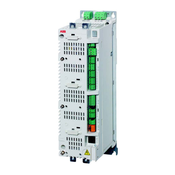
This chapter describes the construction and operating principle of the drive in short. The ACSM1-04 The ACSM1-04 is an IP20 drive module for controlling AC motors. It is to be installed into a cabinet by the customer. The ACSM1-04 either has an air-cooled heatsink, or is to be installed on a “cold plate”... -
Page 22: Main Circuit And Control Interfaces
Memory unit (JMU) containing the application program (see page 69) AC supply CHK-xx mains choke (optional) UDC+ UDC- V1 W1 JFI-xx mains filter (optional) ACSM1-04 Rectifier – Capacitor bank Inverter Braking chopper V2 W2 Motor output JBR-xx braking resistor (optional) The ACSM1-04... -
Page 23: Operation
Description Braking chopper Conducts the energy generated by a decelerating motor from the DC bus to a braking resistor. The braking chopper is built in the ACSM1; braking resistors are external options. Braking resistor Dissipates the regenerative energy by converting it to heat. - Page 24 The ACSM1-04...
-
Page 25: Planning The Cabinet Assembly
Please note that the installation must, however, always be designed and made according to applicable local laws and regulations. ABB does not assume any liability whatsoever for any installation which breaches the local laws and/or other regulations. -
Page 26: Main Dimensions And Free Space Requirements
Main dimensions and free space requirements The modules can be installed side by side. The main dimensions of the drive modules as well as free space requirements are shown below. For more details, refer to the chapter Dimension drawings. Frame D Frame C Frame B Frame A... -
Page 27: Cooling And Degrees Of Protection
200 [7.9”] 300 [12”] The temperature of the cooling air entering the unit must not exceed the maximum allowed ambient temperature (see Ambient conditions in the chapter Technical data). Consider this when installing heat-generating components (such as other drives, mains chokes and braking resistors) nearby. Cooling and degrees of protection The cabinet must have enough free space for the components to ensure sufficient cooling. - Page 28 • allowed ambient temperature • cold plate specification (for ACSM1-04Cx-xxxx-x only). Make sure the air inlets and outlets are sufficient in size. Please note that in addition to the power loss of the drive module, the heat dissipated by cables and other additional equipment must also be ventilated.
-
Page 29: Preventing The Recirculation Of Hot Air
Preventing the recirculation of hot air Cabinet (side view) AREA Main airflow out Air baffle plates COOL AREA Main airflow in Outside the cabinet Prevent hot air circulation outside the cabinet by leading the outcoming hot air away from the area where the inlet air to the cabinet is taken. Possible solutions are listed below: •... - Page 30 Planning the cabinet assembly...
-
Page 31: Mechanical Installation
Mechanical installation Contents of the package The drive is delivered in a cardboard box. To open, remove any banding and lift the top off the box. Mechanical installation... - Page 32 The box contains: • ACSM1-04 drive module, with factory-installed options • three cable clamp plates (two for power cabling, one for control cabling) with screws • screw-type terminal blocks to be attached to the headers on the JCU Control Unit and the power unit •...
-
Page 33: Delivery Check And Drive Module Identification
Technical data for the allowed operation conditions of the drive. The ACSM1-04 is to be mounted in an upright position. The wall the drive is to be mounted on must be as even as possible, of non-flammable material and strong enough to carry the weight of the drive. -
Page 34: Installation Procedure
Installation procedure Direct wall mounting 1. Mark the locations for the four holes. The mounting points are shown in Dimension drawings. 2. Fix the screws or bolts to the marked locations. 3. Position the drive onto the screws on the wall. Note: Only lift the drive by its chassis. -
Page 35: Cold Plate Mounting (Acsm1-04Cx-Xxxx-X, Frames C And D Only)
Cold plate mounting (ACSM1-04Cx-xxxx-x, frames C and D only) For cold plate cooling characteristics, see page 74. 1. Determine the locations for the four fixing points on the cold plate. The fixing points of the drive module are shown in the dimension drawings on page (frame C) or (frame D). -
Page 36: Mains Filter Installation
Mains filter installation See the chapter Mains filters on page 87. Braking resistor installation See the chapter Resistor braking on page 91. Mechanical installation... -
Page 37: Planning The Electrical Installation
Note: The installation must always be designed and made according to applicable local laws and regulations. ABB does not assume any liability whatsoever for any installation which breaches the local laws and/or other regulations. -
Page 38: Other Regions
The protective characteristics of circuit breakers depend on the supply voltage as well as the type and construction of the breakers. There are also limitations pertaining to the short-circuit capacity of the supply network. Your local ABB representative can help you in selecting the breaker type when the supply network characteristics are known. -
Page 39: Ground Fault Protection
The user can tune the thermal model further by feeding in additional motor and load data. The ACSM1-04 has a dedicated connection for PTC or KTY84 sensors. See page in this manual, and the appropriate Firmware Manual for the parameter settings concerning motor thermal protection. -
Page 40: Safe Torque Off
(see diagram below). By using this function, short-time operations (like cleaning) and/or maintenance work on non- electrical parts of the machinery can be performed without switching off the power supply to the drive. ACSM1-04 X6:1 +24 V X6:2... -
Page 41: Selecting The Power Cables
Selecting the power cables General rules Dimension the supply (input power) and motor cables according to local regulations. • The cable must be able to carry the drive load current. See the chapter Technical data for the rated currents. ° •... -
Page 42: Motor Cable Shield
Motor cable shield To function as a protective conductor, the shield must have the same cross-sectional area as a phase conductor when they are made of the same metal. To effectively suppress radiated and conducted radio-frequency emissions, the shield conductivity must be at least 1/10 of the phase conductor conductivity. The requirements are easily met with a copper or aluminium shield. -
Page 43: Residual Current Device (Rcd) Compatibility
Relay output Residual current device (RCD) compatibility ACSM1-04 drives are suitable to be used with residual current devices of Type B. Other measures for protection in case of direct or indirect contact, such as separation from the environment by double or reinforced insulation or isolation from the supply system by a transformer, can also be applied. -
Page 44: Selecting The Control Cables
Control panel cable The cable connecting the control panel to the drive must not exceed 3 metres in length. The cable type tested and approved by ABB is used in control panel option kits. Connection of a motor temperature sensor to the drive I/O See page 60. -
Page 45: Control Cable Ducts
Where control cables must cross power cables make sure they are arranged at an angle as near to 90 degrees as possible. Do not run extra cables through the drive. The cable trays must have good electrical bonding to each other and to the grounding electrodes. - Page 46 Planning the electrical installation...
-
Page 47: Electrical Installation
Electrical installation What this chapter contains This chapter describes the electrical installation procedure of the drive. WARNING! The work described in this chapter may only be carried out by a qualified electrician. Follow the Safety instructions on the first pages of this manual. Ignoring the safety instructions can cause injury or death. -
Page 48: Braking Resistor Assembly
Braking resistor assembly Check the insulation of the braking resistor assembly (if present) as follows: 1. Check that the resistor cable is connected to the resistor, and disconnected from the drive output terminals R+ and R-. 2. At the drive end, connect the R+ and R- conductors of the resistor cable together. Measure the insulation resistance between the combined conductors and the PE conductor by using a measuring voltage of 1 kV DC. -
Page 49: Power Cable Connection
Mains chokes (page 85). JFI-xx mains filter (optional). See the chapter Mains filters (page 87). The UDC+/UDC– connectors can be used for common DC configurations. See page 56. ACSM1-04 UDC+ UDC– R– Optional braking resistor (see the chapter Resistor braking... -
Page 50: Procedure
Procedure Cabling drawings with tightening torques for each frame size are presented on pages to 55. 1. Frame sizes C and D only: Remove the two plastic connector covers at the top and bottom of the drive. Each cover is fastened with two screws. 2. -
Page 51: Grounding The Motor Cable Shield At The Motor End
13. Ground the other end of the supply cable shield or PE conductor(s) at the distribution board. In case a mains choke and/or a mains filter is installed, make sure the PE conductor is continuous from the distribution board to the drive. Grounding the motor cable shield at the motor end For minimum radio frequency interference, ground the cable shield 360 degrees at the lead-through of the motor terminal box... -
Page 52: Installation Of Power Cable Clamp Plates
Installation of power cable clamp plates Two identical power cable clamp plates are included with the drive. The picture below depicts a frame size A drive; the installation is similar with other frame sizes. Note: Pay attention to supporting the cables adequately within the installation enclosure especially if not using the cable clamps. -
Page 53: Power Cable Connection - Frame Size A
Power cable connection – frame size A Supply cable Cable clamp on bare shield 1.5 N·m (13 lbf·in) Below cable clamp, cover bare shield with insulating tape 1.5 N·m (13 lbf·in) 0.5 … 0.6 N·m (4.4 … 5.3 lbf·in) 0.5 … 0.6 N·m (4.4 … 5.3 lbf·in) 1.5 N·m (13 lbf·in) Above cable clamp, cover bare shield with insulating tape... -
Page 54: Power Cable Connection - Frame Size B
Power cable connection – frame size B Supply cable Cable clamp on bare shield 1.5 N·m (13 lbf·in) Below cable clamp, cover bare shield with insulating tape 1.5 N·m (13 lbf·in) 1.2 … 1.5 N·m (10.6 … 13.3 lbf·in) 1.5 N·m (13 lbf·in) Above cable clamp, cover bare shield with insulating tape Cable clamp on bare shield... -
Page 55: Power Cable Connection - Frame Sizes C And D (Connector Covers Removed)
Power cable connection – frame sizes C and D (connector covers removed) Supply cable Screw lug detail Below cable clamp, cover bare Cable clamp on bare shield shield with insulating tape 15 N·m (11 lbf·ft) 1.5 N·m (13 lbf·in) 3 N·m (25 lbf·in) 15 N·m (11 lbf·ft) -
Page 56: Dc Connection
DC connection The UDC+ and UDC– terminals are intended for common DC configurations of a number of ACSM1 drives, allowing regenerative energy from one drive to be utilised by the other drives in motoring mode. One or more drives are connected to the AC supply depending on the power requirement. - Page 57 Each drive has an independent DC capacitor pre-charging circuit. UDC+ UDC- V1 W1 – Pre-charging circuit V2 W2 The ratings of the DC connection are given on page 76. Electrical installation...
-
Page 58: Connecting The Control Cables
Connecting the control cables Control connections to the JCU Control Unit Notes: +24VI External power input *Total maximum current: 200 mA 24 V DC, 1.6 A The wiring shown is for demonstrative purposes only. Refer to the Relay output appropriate Firmware Manual for 250 V AC / 30 V DC default I/O assignments. -
Page 59: Jumpers
Jumpers J1 – Determines whether Analogue input AI1 is used as a current or voltage input. Current Voltage J2 – Determines whether Analogue input AI2 is used as a current or voltage input. Current Voltage J3 – Drive-to-drive link termination. Must be set to the ON position when the drive is the last unit on the link. -
Page 60: Thermistor Input (X4:8
Thermistor input (X4:8…9) Motor temperature can be measured using PTC or KTY84 sensors connected to the thermistor input. One PTC or KTY84 sensor Three PTC sensors Motor Motor AGND AGND 10 nF 10 nF WARNING! As the thermistor input on the JCU Control Unit is not insulated according to IEC 60664, the connection of the motor temperature sensor requires double or reinforced insulation between motor live parts and the sensor. -
Page 61: Control Cable Grounding
Control cable grounding The shields of all control cables connected to the JCU Control Unit must be grounded at the control cable clamp plate. Use four M4 screws to fasten the plate as shown below left. The plate can be fitted either at the top or bottom of the drive. The shields should be continuous as close to the terminals of the JCU as possible. -
Page 62: Installation Of Options
Installation of options Options such as fieldbus adapters, I/O extensions and encoder interfaces are inserted into slots on the JCU Control Unit. See page for the available slots; see the appropriate option manual for specific installation and wiring instructions. Electrical installation... -
Page 63: Installation Checklist
Planning the electrical installation, Electrical installation.) The VAR screw is removed if the drive is connected to an IT (ungrounded) supply network. The capacitors are reformed if stored over one year (ask local ABB representative for more information). The drive is grounded properly. - Page 64 Check The supply (input power) voltage cannot be applied to the output of the drive through a bypass connection. Motor connection box and other covers are in place. Installation checklist...
-
Page 65: Maintenance
Ignoring the safety instructions can cause injury or death. Maintenance intervals If installed in an appropriate environment, the drive requires very little maintenance. This table lists the routine maintenance intervals recommended by ABB. Maintenance Interval Instruction... -
Page 66: Cooling Fan
If the drive is operated in a critical part of a process, fan replacement is recommended once these symptoms start appearing. Replacement fans are available from ABB. Do not use other than ABB-specified spare parts. -
Page 67: Fan Replacement (Frames C And D, Acsm1-04Ax-Xxxx-X)
Fan replacement (Frames C and D, ACSM1-04Ax-xxxx-x) To remove the fan, release the retaining clip (arrowed) carefully using a screwdriver. Pull the fan holder out. Disconnect the fan cable. Carefully bend the clips on the fan holder to free the fan. -
Page 68: Fan Replacement (Frames C And D, Acsm1-04Cx-Xxxx-X)
Fan replacement (Frames C and D, ACSM1-04Cx-xxxx-x) Unfasten the fan holder by removing the two screws marked (1) in the drawing below. Pull the fan holder out and disconnect the wire plug (2). Remove the four screws (3) to release the fan from the holder. Use the spacers (4) to mount the new fan. -
Page 69: Reforming The Capacitors
The capacitors must be reformed if the drive has been stored for a year or more. See page for information on finding out the manufacturing date. For information on reforming the capacitors, contact your local ABB representative. Other maintenance actions Transferring the memory unit to a new drive module When a drive module is replaced, the parameter settings can be retained by transferring the memory unit from the defective drive module to the new module. - Page 70 Maintenance...
-
Page 71: Technical Data
This chapter contains the technical specifications of the drive, e.g. the ratings, sizes and technical requirements, and provisions for fulfilling the requirements for CE and other markings. Ratings The nominal current ratings for the ACSM1-04 with 400 V AC supply are given below. Input ratings Output ratings... -
Page 72: Derating
Derating The continuous output currents stated above must be derated if any of the following conditions apply: • the ambient temperature exceeds +40 °C (+104°F) • the AC supply voltage is higher than 400 V • the drive is installed higher than 1000 m above sea level. Note: The final derating factor is a multiplication of all applicable derating factors. -
Page 73: Cyclic Loads
The above procedure can also be applied to longer load cycles by dividing the cycle into subcycles no longer than 10 seconds. If any of the subcycles fail the test, a more detailed study is required. The DriveSize dimensioning tool available from ABB is recommended for more detailed dimensioning. Technical data... -
Page 74: Dimensions And Weights
/min, the cooling is adequate. The temperature rise of the coolant due to the drive is approximately 1…2 K maximum. The ACSM1-04Cx-xxxx-x has an internal fan to cool the circuit boards. The heat dissipation into air is approximately 200 W. Technical data... -
Page 75: Supply Cable Fuses
Note: Fuses with a higher current rating must not be used. Cross-sectional IEC fuse UL fuse area of cable Input Drive type current Rated Rated ACSM1-04xx… current Voltage Class current Voltage Class -02A5-4 3.2* 1.5 … 4 16…12 -03A0-4 4.7*... -
Page 76: Ac Input (Supply) Connection
Frames C and D: Screw lugs for 6…70 mm wire included. Suitable crimp lugs can be used instead. DC connection Voltage 436 … 712 V DC Ratings Drive type ACSM1-04xx… (µF) -02A5-4 -03A0-4 -04A0-4 -05A0-4 -07A0-4 -09A5-4 -012A-4 -016A-4... -
Page 77: Jcu Control Unit
Terminals Frame A: Detachable screw terminal block for 0.25 … 4 mm wire. Frame B: Detachable screw terminal block for 0.5 … 6 mm wire. Frames C and D: Screw lugs for 6…70 mm wire included. Suitable crimp lugs can be used instead. -
Page 78: Efficiency
Reference voltage (VREF) Connector pitch 3.5 mm, wire size 1.5 mm for analogue inputs 10 V ±1% and –10 V ±1%, R > 1 kohm load Drive to drive link (X5) Connector pitch 3.5 mm, wire size 1.5 mm Physical layer: RS-485 Termination by jumper Safe Torque Off connection Connector pitch 3.5 mm, wire size 1.5 mm... -
Page 79: Ambient Conditions
The DC capacitors contain electrolyte, which is classified as hazardous waste within the EU. They must be removed and handled according to local regulations. For further information on environmental aspects and more detailed recycling instructions, please contact your local ABB distributor. Technical data... -
Page 80: Applicable Standards
Part 5-1: Safety requirements. Electrical, thermal and energy Provisions for compliance: The final assembler of the machine is responsible for installing the ACSM1-04 in a cabinet that is protected to IP2X (IP3X for top surfaces for vertical access). • prEN 61800-5-2 Adjustable speed electrical power drive systems. -
Page 81: Ce Marking
CE marking A CE mark is attached to the drive to verify that the drive follows the provisions of the European Low Voltage and EMC Directives (Directive 73/23/EEC, as amended by 93/68/EEC, and Directive 89/336/ EEC, as amended by 2004/108EC). Compliance with the European Low Voltage Directive The compliance with the European Low Voltage Directive has been verified according to standards EN 50178, EN 61800-5-1 and EN 60204-1. -
Page 82: Compliance With En 61800-3 (2004), Category C3
The drive is intended to be incorporated into machinery to constitute machinery covered by Machinery Directive (98/37/EC) and does therefore not in every respect comply with the provisions of the directive. For more information, see the Declaration of Incorporation by ABB Drives (code 64652770). C-Tick marking Pending. -
Page 83: Ul Marking
Overload protection – The drive provides overload protection in accordance with the National Electrical Code (US). Braking – The ACSM1-04 has an internal braking chopper. When applied with appropriately sized braking resistors, the braking chopper will allow the drive to dissipate regenerative energy (normally associated with quickly decelerating a motor). - Page 84 Technical data...
-
Page 85: Mains Chokes
Mains chokes What this chapter contains This chapter describes how to select and install mains chokes for the ACSM1-04. The chapter also contains the relevant technical data. When is a mains choke required? The ACSM1-04 does not necessarily require a mains choke for operation; the need for a choke should be determined on a case-by-case basis. -
Page 86: Installation Guidelines
• Keep the cable between the drive and the choke as short as possible. WARNING! The surface of the mains choke becomes hot when in use. Connection diagram AC supply CHK-xx mains choke JFI-xx mains filter (if present) ACSM1-04 Mains chokes... -
Page 87: Mains Filters
Not applicable restricted distribution A mains filter is required in order to meet the category C2 level with the ACSM1 drive installation, including a motor with a max. 50 m cable. This level corresponds to the A limits for Group 1 equipment according to EN 55011. -
Page 88: Selection Table
Selection table Mains filters for ACSM1-04 Drive type Filter type ACSM1-04xx… -02A5-4 -03A0-4 -04A0-4 JFI-02 -05A0-4 -07A0-4 -09A5-4 -012A-4 JFI-03 -016A-4 -024A-4 -031A-4 JFI-05 -040A-4 -046A-4 -060A-4 -073A-4 JFI-07 -090A-4 PDM-425726 The mains filters are protected to IP20. Refer to page for dimensions, wire sizes and tightening torques. -
Page 89: Connection Diagram
Connection diagram AC supply CHK-xx mains choke (if present) JFI-xx mains filter L1’ L2’ L3’ ACSM1-04 Mains filters... - Page 90 Mains filters...
-
Page 91: Resistor Braking
2. Calculate the continuous power based on the braking duty cycle. 3. Calculate the braking energy during the duty cycle. Pre-selected resistors are available from ABB as shown in the table below. If the listed resistor is not sufficient for the application, a custom resistor can be selected within the limits imposed by the internal braking chopper of the ACSM1-04. -
Page 92: Chopper Data / Resistor Selection Table
Contactor protection of drive below. Chopper data / Resistor selection table The ratings apply at an ambient temperature of 40°C (104°F). Internal braking chopper Example braking resistor Drive type brcont brmax pulse ACSM1-04xx… Type (kW) (kW) (ohm) (ohm) (kJ) -02A5-4 -03A0-4 JBR-01... -
Page 93: Resistor Installation And Wiring
Below is a simple example wiring diagram. L1 L2 L3 Fuses ACSM1 U1 V1 W1 Resistor thermal switch Θ Resistor braking... -
Page 94: Braking Circuit Commissioning
Braking circuit commissioning For more information, see the appropriate Firmware Manual. • Enable the braking chopper function. Please note that a braking resistor must be connected when the chopper is enabled • Switch off the overvoltage control of the drive •... -
Page 95: Dimension Drawings
Dimension drawings What this chapter contains Dimension drawings of the ACSM1-04 and related accessories are shown below. The dimensions are given in millimetres and [inches]. Dimension drawings... -
Page 96: Frame Size A
Frame size A Dimension drawings... - Page 97 Dimension drawings...
-
Page 98: Frame Size B
Frame size B Dimension drawings... - Page 99 Dimension drawings...
-
Page 100: Frame Size C (Air-Cooled Module)
Frame size C (air-cooled module) Dimension drawings... - Page 101 Dimension drawings...
-
Page 102: Frame Size C (For Cold Plate Mounting)
Frame size C (for cold plate mounting) Dimension drawings... -
Page 103: Frame Size D (Air-Cooled Module)
Frame size D (air-cooled module) Dimension drawings... -
Page 104: Frame Size D (For Cold Plate Mounting)
Frame size D (for cold plate mounting) Dimension drawings... -
Page 105: Mains Chokes (Type Chk-0X)
Mains chokes (type CHK-0x) 68906903 CHK-xx dimensions Choke type Parameter CHK-01 CHK-02 CHK-03 CHK-04 CHK-05 CHK-06 CHK-07 CHK-08 dim A mm (in.) 120 (4.72) 150 (5.91) 150 (5.91) 150 (5.91) 207 (8.15) 207 (8.15) 249 (9.80) 249 (9.80) dim B mm (in.) 146 (5.75) 175 (6.89) 175 (6.89) 175 (6.89) 272 (10.71) 326 (12.83) 326 (12.83) 346 (13.62) dim C mm (in.) 79 (3.11) 86 (3.39) 100 (3.94) 100 (3.94) 154 (6.06) -
Page 106: Mains Filters (Type Jfi-Xx)
Mains filters (type JFI-xx) Dimension drawings... - Page 107 Dimension drawings...
-
Page 108: Braking Resistors (Type Jbr-Xx)
Braking resistors (type JBR-xx) Dimension drawings... - Page 109 Dimension drawings...
- Page 110 Dimension drawings...
- Page 112 ABB Oy AC Drives P.O. Box 184 FI-00381 HELSINKI FINLAND Telephone +358 10 22 11 +358 10 22 22681 Internet http://www.abb.com...
Need help?
Do you have a question about the ACSM1 and is the answer not in the manual?
Questions and answers