
Related Manuals for KYLAND KIEN8000


Summary of Contents for KYLAND KIEN8000
- Page 1 KIEN8000 Industrial Ethernet Switch User’s Manual KYLAND Telecom Technology Co., Ltd.
- Page 2 Copyright © 2005 KYLAND Telecom Technology CO., LTD. All rights reserved. No part of this documentation may be excerpted, reproduced, translated, annotated or duplicated, in any form or by any means without the prior written permission of KYLAND Corporation. Publisher: KYLAND Telecom Technology Co., Ltd.
- Page 3 Ethernet switches for user’s reference on system opening, expansion and routine maintenance. It is also applicable to training to users and study of related technicians. It is a practical book for users to know and understand KIEN8000 industrial Ethernet switches.
- Page 4 Safety Notices This product can provide excellent and reliable performance within its design scope. However, it needs to avoid the damage or destroy by human reasons. Read this Manual thoroughly and keep it well for future reference. Do not place the equipment next to the source of water and the damp place. ...
- Page 5 Description of Warning Mark: This manual uses two kinds of obvious warning marks to prompt users that more attention should be paid during operation. The meanings of these marks as follows: Warning: The comment after this mark should be paid more attention, the incorrect operation will cause the switch to be damaged seriously or it will cause body injury for the operator.
-
Page 7: Table Of Contents
CONTENTS Chapter 1: System Overview ......................... 1 1.1 Product Overview ........................... 1 1.2 System Features ............................1 1.3 Packing List and Unpacking Check ....................... 2 Section 2: Performance Specifications ......................4 1.4 System Specifications ..........................4 1.5 Service Interface ............................. 5 1.6 Service Functions ........................... - Page 8 1.16 System Configurations ........................25 Appendix A Twisted-pair and Pin Distribution ..................26 -II-...
-
Page 9: Chapter 1: System Overview
300MA. Each Ethernet port of KIEN8000-RJ45(P) is adaptive to 10Base-T or 100Base-TX, e, it can also do auto MDI/MDI-X connection. Each Ethernet port of KIEN8000-M12(P) is fixed at 10Base-T and adaptive to half-duplex or full-duplex mode, it can be auto MDI/MDI-X connected too. -
Page 10: Packing List And Unpacking Check
Packing List The packing box includes the following: KIEN8000 M12 power terminal M12 Ethernet terminal IP67 accessories for KIEN8000-M12(P) RJ45 Ethernet terminal IP67 accessories for KIEN8000-RJ45(P) User’s Manual of KIEN8000 Industrial Ethernet Switches Customer Service Guide Ф3 grounded cold pressure terminal and M3×8 grounded screw Unpacking Check Before unpacking, place the box on level floor. - Page 11 Kyland Telecom Warning: The switch contains fine components. Please handle it softly and avoid intense vibration lest switch performance is affected.
-
Page 12: System Specifications
Section 2: Performance Specifications 1.4System Specifications The system specifications of KIEN8000 industrial Ethernet switch is shown as table 2-1. Table 2-1 System Specifications Specs Description 8 ×10Base-T/100Base-TX Port Type and Quantity Standard: IEEE802.3、IEEE 802.3x、IEEE 802.3u Storage and forward rate: 148810 pps... -
Page 13: Service Interface
2. The Ethernet port is ableo to source DC24V power supply with max 300MA current. 3. Conform to IEEE802.3/802.3U/802.3X. 1.6Service Functions KIEN8000 offers such service functions as following: 1. LED Indicator The LEDs of the front panel indicate the port status correctly including transmission rate, link status and system status. -
Page 15: System Structure
1.8Switch Structure 1.8.1Chassis The chassis of KIEN8000 is structured for wall mounting or DIN rail mounting. The switch is covered completely for six sides to reach IP67 protection class. The aluminum-made chassis is one part of the heat dissipation system. The heat generated... -
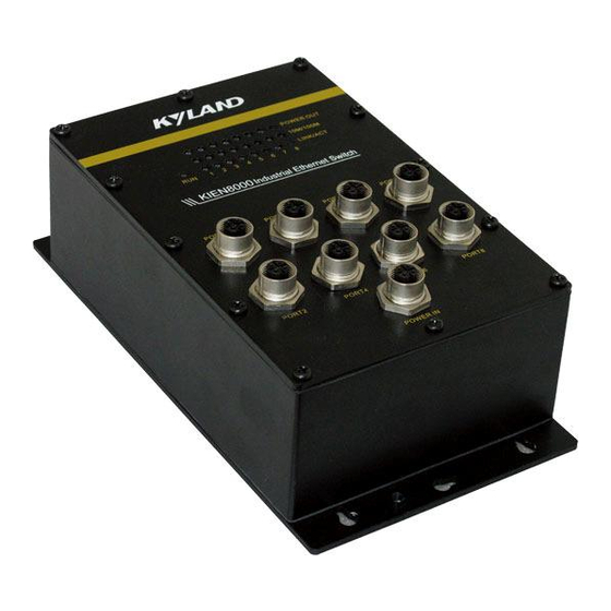
Page 16: Front Panel
It discards the traditional axial flow fan and reduces total power consumption but increases system stability. The chassis of KIEN8000 is shown in the Figure 3-2: Dimensions:142㎜55.4㎜120.5㎜(H×W×D):215㎜120㎜66㎜... - Page 17 M12 terminal. For KIEN8000-RJ45(P), the 8 M12 Ethernet ports are also fixed in the front panel. The 8 RJ45 Ethernet ports are in the side of the chassis of KIEN8000-RJ45(P). Its structure is showed in the Figure 3-3: a.
- Page 18 Ports have network activity. Ports have no effective network connection. Power Connector M12 The power terminal of KIEN8000 is M12 of IP67 protection class. Its appearance is shown in Figure 3-4: Figure 3-4 M12 Power Connector M12 power terminal has five pins for input of DC24V, the pins are positioned as...
- Page 19 Figure 3-6 M12 Terminal Plug Grouding Protection There are a tread hole at the bottom panel of KIEN8000 and a Ф3 grounded cold pressure terminal and M3×8 grounded screw enclosed with the switch. As shown in Figure 3-7, connect one end of grounding cable with the cold pressure terminal and fix it on the grounding hole of swtich by screw.
-
Page 20: Rj45 Ethernet Port
Picture3-7 KIEN8000 Grounding Method 1.8.3RJ45 Ethernet Port KIEN8000-RJ45(P) offers 8 RJ45 IP67 ports of 10Base-T/100Base-TX which may be power sourcing or not. Each port is adaptive and support for auto MDI/MDI-X connection. The switch can be connected to terminal device or other switches by straight-through or cross-over cables. - Page 21 Figure 3-8 RJ45 Terminal Connector Each RJ45 Ethernet of the power sourcing KIEN8000 offers DC24V power supply for remote Ethernet device or PD with max 300MA current. The cable wiring way is shown in Figure 3-9: KI EN 8000 - R J45...
- Page 22 Figure 3-11 RJ45Connector and Crystal Head 3、 Press the crystal head into the terminal and keep the rings closely as shown in Figure 3-12: Figure 3-12 Assembled RJ45 Connector 4、 Press the assembled RJ45 connector into the RJ45 socket of KIEN8000- -12-...
-
Page 23: M12 Ethernet Port
Figure 3-13 RJ45 Connector Into RJ45 Socket 1.8.4M12 Ethernet Port KIEN8000-M12(P) offers 8 M12 ports of 10Base which may be power sourcing or not. Each port is adaptive and support for auto MDI/MDI-X connection. The switch can be connected to terminal device or other switches by straight-through or cross-over cables. - Page 24 KIEN8000 User Manual Ethernet M12 Terminal Pin Definition: -pin 1:TX+,( Sourcing DC24V+) -pin 3:TX-,( Sourcing DC24V+) -pin 2:RX+,(Sourcing DC24V-) -pin 4:RX-,(Sourcing DC24V-) picture3-14 Ethernet M12 Terminal Pin -14-...
-
Page 25: Section 4 :Hardware Mounting
4. Avoid direct sunshine and keep it away from heating sources or areas where have strong electromagnetic interference. 5. Standard products of KIEN8000 only provides DIN rail mounting parts. Users need to prepare DIN rails. But if the wall mounting is required, users need to purchase the wall mounting part additionally. - Page 26 DIN rail-connecting position has already been fixed on the rear panel of KIEN8000. The Figure 4-1 shows the size of rail-type mounting. If you want to mount the switch on the DIN rail, please check mounting of the DIN rail before mounting the switch.
- Page 27 In case that DIN rail-type mounting is inconvenient, it is better to adopt wall mounting. KYLAND Telecom provides users with wall mounting boards that are mounting parts for mounting of KIEN8000. The size of wall mounting is shown in the Figure 4-3 and 4-4.
-
Page 28: Wall Mounting
KIEN8000 User Manual Figure 4-3 KIEN8000’s 1 wall-mounting dimensions -18-... - Page 29 Figure 4-4 KIEN8000’s 2 wall-mounting dimensions The steps of wall mounting of KIEN8000 are as follows: 1. Unfasten four screws on the switch which is used to fix the DIN rail connecting seat with a cross head screwdriver and dismantle the green DIN rail connecting seat.
-
Page 30: Connecting Cable
After the switch is mounted correctly, cable connection can be made, which mainly include cable connection of the following ports: 1. Service Ports The service ports of KIEN8000 are power sourcing RJ45 or M12 Ethernet ports offering DC24V to terminal Ethernet devices via straight-through cable or to powered devices via cross-over cable. -
Page 31: Cables Wiring
Kyland Telecom 1.12Cables Wiring Wiring shall accord with following conditions: 1. Before laying, verify accordance of the specification, model and quantity of all cables and wires with construction drawings and requirements under the contract. 2. Before laying, check whether cables and wires are damaged and ensure they have ex-works records and quality guarantee, and other certificates that prove their quality. -
Page 32: Section 5: Testing Methods
RUN indicator is on. 1.14Testing Ethernet Ports As shown in Figure 5-1, KIEN8000 is powered up and any two Ethernet ports are connected to the uplink Ethernet ports of KIEN1000-PD(powered device) by cross- over or straight-through cables. Any port of the PD is connected to the Ethernet port of PC. - Page 33 第 5 章 PING Command The IP address of the testing computer 1 is 192.168.100.10 and the 2 is 192.168.100.11.On the testing computer 1, run “cmd” in the WIN2000 operating system or “command” in the WIN98/95 operating system from “Run” in the “Start” menu.
-
Page 34: Networking
System Configuration 1.15Networking KIEN8000 offers 8 power-sourcing or not RJ45 ports 10Base-T/100Base-TX or 8 power-sourcing or not M12 ports 10Base-T, each port can be connected to remote Ethernet devices offering max 300MA current or to the uplink port of KIEN1000B- PD(powered devide) to form a star topology. - Page 35 Kyland Telecom 第六章 组网方式和系统配置 1.16System Configurations KIEN8000 is structured integrative. 8 RJ45 or M12 Ethernet ports are fixed and can be power sourcing or not. Power supply is fixed at DC24V. The detailed model and description is shown as figure 6-1:...
- Page 36 Appendix A Twisted- pair and Pin Distribution For the 10Base-T/100Base-TX, the twisted-pair should present two pair of wires. Each pair is differentiated by different colors. For instance, the one is green and the other is the green and white interleaved. There should be the RJ-45 connector at both sides of cables.
- Page 37 The RJ-45 port supports the automatic MDI/MDI-X operation, and can use the direct connection wire to connect the PC or server, or connect other switches or hubs. In the direct connection wire, pin 1, 2, 3 and 6 are at the same end of the cable and are connected to the pin 1, 2, 3 and 6 at the other end of the connection cable.
- Page 38 2828 Appendix B Glossary Terminology Explanation Twisted-pair standard of Cat3, Cat4 and Cat5 in IEEE specification for 10Base-T 10Mbps Ethernet Twisted-pair standard of Cat5 or above in IEEE specification for 100Base-TX 100Mbps Fast Ethernet Fast Ethernet which uses one pair of multi-mode or single mode optical 100Base-F...
Need help?
Do you have a question about the KIEN8000 and is the answer not in the manual?
Questions and answers