Sony WRU-806B Service Manual
Uhf synthesized tuner unit
Hide thumbs
Also See for WRU-806B:
- Operating instructions (2 pages) ,
- Operating instructions (2 pages)

Related Manuals for Sony WRU-806B


Summary of Contents for Sony WRU-806B
- Page 1 UHF SYNTHESIZED TUNER UNIT WRU-806B SERVICE MANUAL 2nd Edition Serial No. 104001 and Higher: WRU-806B (U30) Serial No. 104001 and Higher: WRU-806B (U42) Serial No. 421001 and Higher: WRU-806B (CE38)
- Page 2 Ce manual est destiné uniquement aux personnes compétentes en charge de l’entretien. Afin de réduire les risques de décharge électrique, d’incendie ou de blessure n’effectuer que les réparations indiquées dans le mode d’emploi à moins d’être qualifié pour en effectuer d’autres. Pour toute réparation faire appel à une personne compétente uniquement. WRU-806B...
-
Page 3: Table Of Contents
RF-155 ................5-1 1. Service Overview 6. Schematic Diagrams 1-1. Boards Location .............. 1-1 DP-476 ................6-1 1-2. WRU-806B Removal ............1-1 RF-155 ................6-2 1-3. WRU-806B Checking ............. 1-1 1-4. Error Messages ............... 1-2 1-5. Setting / Release of Muting Function ......1-2 1-6. -
Page 5: Manual Structure
Related manuals The following manuals are available in this model. If this manual is required, please contact your local Sony Sales Office/Service Center..Instruction Manual (Supplied with units) This manual is necessary for application and operation of units. -
Page 7: Service Overview
RF-155 board Equipment Required : MB-X6 (quality unit) WRU-806B (quality unit) (1) Install the repair WRU-806B to be examined in a quali- ty MB-X6. (2) Check the fault with a quality MB-X6. . If there is a fault, WRU-806B (repair unit) is defective. -
Page 8: Error Messages
Set or release the following functions by operating the button on the front panel of the WRU-806B installed in the MB-X6. The muting function can be set and released separately for tuner [1] to [6] . (Tuner [1] to [6] ; when WRU-806B installed in the MB-X6.) -
Page 9: Electrical Alignment
1 (Part No. 1-562-261-21) BNC-P connector; 1 (Part No. 1-560-257-11) Ceramic capacitor 0.001 uF ; 1 (Part No. 1-161-456-00) Ceramic capacitor BNC-J connector BNC-P connector 0.001 uF 50 V (1-161-456-00) (1-562-261-21) (1-560-257-11) Plated wire (0.6 to 0.8 ø) 2 mm Solder WRU-806B... -
Page 10: Adjustments
The RF level of the input signal (the output level of the sig- nal generator) for adjustment is expressed as an open ended (0 dBu = 1 uV voltage in unit dBuV The adjustment is to be performed by calibrating the output level of the signal generator as shown below. WRU-806B... -
Page 11: Muting Level And Rf Level Adjustment
(to be adjusted) is installed into the Tuner [1] slot on the 2. Remove the upper side case lid of the tuner unit (WRU-806B to be adjusted), and insert the tuner unit MB-X6. (WRU-806B) to the Tuner [1] slot of the MB-X6. - Page 12 (13) Check first that indication “L” of “AC3L” on the LCD (WRU-806B, Tuner [1]) has disappeared, and then (WRU-806B, Tuner [1]) has disappeared, and then press the “CH” button on the front panel (WRU-806B, Tuner [1]). press the “CH” button on the front panel (WRU-806B, Tuner [1]).
-
Page 13: Output Level Adjustment
(23)Check first that indication “L” of “BC3L” on the LCD Perform this adjustment when the TUNER OUTPUT levels (WRU-806B, Tuner [1]) has disappeared, and then deviate from the specification. press the “CH” button on the front panel (WRU-806B, Tuner [1]). Preparation (24)Transit from indication “BACKUP” to indication “FIN- Before the adjustments, turn off the POWER switch of the ISH”, and then indication on the LCD (WRU-806B,... - Page 14 Channel setting : switch and perform the followings. CE38 model ; Group 00, 3932 channel (618.000 MHz) (1) Remove the tuner unit WRU-806B to be adjusted from U30 model ; Group 00, 3201 channel (578.125 MHz) the MB-X6. U42 model ; Group 00, 4401 channel (650.125 MHz)
-
Page 15: Overall Characteristics Check
2-2-3. Overall Characteristics Check Connection Microphone Audio analyzer amplifier Perform the check with the WRU-806B installed in the balance MB-X6. input Signal TUNER generator OUTPUT 1 Perform the overall characteristics check according to the following procedure. DC cut fixture Oscilloscope... - Page 16 (12)Check that distortion ratio is _45 dB or less (0.56 % or less) with A-weighted. The checking procedures describe that the WRU-806B (to (13)Connect the signal generator to the ANTENNA B IN be adjusted) is installed into the Tuner [1] slot on the MB- connector with DC cut fixture.
- Page 17 4. Distortion Ratio Check Procedure Procedure The checking procedures describe that the WRU-806B (to The checking procedures describe that the WRU-806B (to be adjusted) is installed into the Tuner [1] slot on the MB- be adjusted) is installed into the Tuner [1] slot on the MB-...
- Page 18 ± 5 dB 45 dBuV Procedure Lighting LCD: The checking procedures describe that the WRU-806B (to be adjusted) is installed into the Tuner [1] slot on the MB- ± 5 dB 55 dBuV Lighting (1) Set the MB-X6 as follows :...
- Page 19 7. Muting Level/RF Indicator Check Procedure Procedure The checking procedures describe that the WRU-806B (to be adjusted) is installed into the Tuner [1] slot on the MB- The checking procedures describe that the WRU-806B (to be adjusted) is installed into the Tuner [1] slot on the MB-...
- Page 20 FREQUENCY (carrier frequency) : CE38 model ; 618.000 MHz U30 model ; 578.125 MHz The checking procedures describe that the WRU-806B (to be U42 model ; 650.125 MHz adjusted) is installed into the Tuner [1] slot on the MB-X6. (= _53 dBm)
- Page 21 Equipment and Tools . DC voltmeter (digital multi meter) . Metal film resistor 91 Z 2W (Part No. 1-214-609-00) The checking procedures describe that the WRU-806B (to be adjusted) is installed into the Tuner [1] slot on the MB- Procedure...
-
Page 23: Spare Parts
Therefore, specified parts should be used in the case of replacement. 2. Standardization of Parts Some repair parts supplied by Sony differ from those used for the unit. These are because of parts common- ality and improvement. 3. Stock of Parts Parts marked with “o”... -
Page 24: Exploded Views
A-1876-191-A s MOUNTED CIRCUIT BOARD, RF-155 (U30) A-1876-759-A s MOUNTED CIRCUIT BOARD, RF-155 (U42) A-1876-761-A s MOUNTED CIRCUIT BOARD, RF-155 (CE38) 1-839-180-11 s CABLE, FLEXIBLE FLAT (36 CORE) 2-347-704-01 s LID 4-995-903-02 s SCREW (B1.4) 7-685-103-19 s SCREW +P 2X5 TYPE2 NON-SLIT WRU-806B... -
Page 25: Electrical Parts List
1-112-692-81 s CAP,CHIP CERAMIC1000PF CH 1005 C215 1-164-847-81 s CAP, CHIP CERAMIC 7PF CH 1005 C216 1-164-847-81 s CAP, CHIP CERAMIC 7PF CH 1005 C217 1-164-874-81 s CAP,CHIP CERAMIC 100PF CH 1005 C218 1-164-858-81 s CAP, CHIP CERAMIC 22PF CH 1005 WRU-806B... - Page 26 1-112-692-81 s CAP,CHIP CERAMIC1000PF CH 1005 C327 1-164-844-81 s CAP, CHIP CERAMIC 4PF CH 1005 C431 1-112-692-81 s CAP,CHIP CERAMIC1000PF CH 1005 C328 1-164-842-81 s CAP,CHIP CERAMIC 2.0PF CK 1005 C435 1-125-777-81 s CAP, CHIP CERAMIC 0.1MF B 1005 WRU-806B...
- Page 27 1-125-777-81 s CAP, CHIP CERAMIC 0.1MF B 1005 FL101 1-200-115-11 s FILTER, BAND PASS 578MHZ C613 1-125-777-81 s CAP, CHIP CERAMIC 0.1MF B 1005 FL201 1-200-115-11 s FILTER, BAND PASS 578MHZ C614 1-164-874-81 s CAP,CHIP CERAMIC 100PF CH 1005 WRU-806B...
- Page 28 1-469-356-21 s INDUCTOR, CHIP 120NH (1005) R132 1-218-929-81 s RES, CHIP 10 L213 1-469-189-21 s INDUCTOR, CHIP 100NH (1005) R133 1-218-959-81 s RES, CHIP 3.3K L219 1-412-959-21 s INDUCTOR, SMALL TYPE 47UH 2520 R137 1-208-875-81 s RES, CHIP 330 (1005) WRU-806B...
- Page 29 1-208-887-81 s RES, CHIP 1.0K (1005) R436 1-208-935-81 s RES, CHIP 100K (1005) R309 1-208-863-81 s RES, CHIP 100 (1005) R437 1-208-895-81 s RES, CHIP 2.2K (1005) R310 1-208-863-81 s RES, CHIP 100 (1005) R438 1-208-951-81 s RES, CHIP 470K (1005) WRU-806B...
- Page 30 1-218-990-81 s CONDUCTOR, CHIP (1005) R655 1-208-863-81 s RES, CHIP 100 (1005) R496 1-208-901-81 s RES, CHIP 3.9K (1005) R656 1-208-889-81 s RES, CHIP 1.2K (1005) R497 1-208-901-81 s RES, CHIP 3.9K (1005) R657 1-208-889-81 s RES, CHIP 1.2K (1005) WRU-806B...
- Page 31 1-112-692-81 s CAP,CHIP CERAMIC1000PF CH 1005 C215 1-164-846-81 s CAP, CHIP CERAMIC 6PF CH 1005 C216 1-164-846-81 s CAP, CHIP CERAMIC 6PF CH 1005 C217 1-164-874-81 s CAP,CHIP CERAMIC 100PF CH 1005 C218 1-164-858-81 s CAP, CHIP CERAMIC 22PF CH 1005 WRU-806B...
- Page 32 1-112-692-81 s CAP,CHIP CERAMIC1000PF CH 1005 C327 1-164-844-81 s CAP, CHIP CERAMIC 4PF CH 1005 C431 1-112-692-81 s CAP,CHIP CERAMIC1000PF CH 1005 C328 1-164-842-81 s CAP,CHIP CERAMIC 2.0PF CK 1005 C435 1-125-777-81 s CAP, CHIP CERAMIC 0.1MF B 1005 3-10 WRU-806B...
- Page 33 1-125-777-81 s CAP, CHIP CERAMIC 0.1MF B 1005 FL101 1-200-118-11 s FILTER, BAND PASS 650MHZ C613 1-125-777-81 s CAP, CHIP CERAMIC 0.1MF B 1005 FL201 1-200-118-11 s FILTER, BAND PASS 650MHZ C614 1-164-874-81 s CAP,CHIP CERAMIC 100PF CH 1005 3-11 WRU-806B...
- Page 34 1-469-356-21 s INDUCTOR, CHIP 120NH (1005) R132 1-218-929-81 s RES, CHIP 10 L213 1-469-189-21 s INDUCTOR, CHIP 100NH (1005) R133 1-218-959-81 s RES, CHIP 3.3K L219 1-412-959-21 s INDUCTOR, SMALL TYPE 47UH 2520 R137 1-208-875-81 s RES, CHIP 330 (1005) 3-12 WRU-806B...
- Page 35 1-208-887-81 s RES, CHIP 1.0K (1005) R436 1-208-935-81 s RES, CHIP 100K (1005) R309 1-208-863-81 s RES, CHIP 100 (1005) R437 1-208-895-81 s RES, CHIP 2.2K (1005) R310 1-208-863-81 s RES, CHIP 100 (1005) R438 1-208-951-81 s RES, CHIP 470K (1005) 3-13 WRU-806B...
- Page 36 1-218-990-81 s CONDUCTOR, CHIP (1005) R655 1-208-863-81 s RES, CHIP 100 (1005) R496 1-208-901-81 s RES, CHIP 3.9K (1005) R656 1-208-889-81 s RES, CHIP 1.2K (1005) R497 1-208-901-81 s RES, CHIP 3.9K (1005) R657 1-208-889-81 s RES, CHIP 1.2K (1005) 3-14 WRU-806B...
- Page 37 1-112-692-81 s CAP,CHIP CERAMIC1000PF CH 1005 C215 1-164-846-81 s CAP, CHIP CERAMIC 6PF CH 1005 C216 1-164-846-81 s CAP, CHIP CERAMIC 6PF CH 1005 C217 1-164-874-81 s CAP,CHIP CERAMIC 100PF CH 1005 C218 1-164-858-81 s CAP, CHIP CERAMIC 22PF CH 1005 3-15 WRU-806B...
- Page 38 1-112-692-81 s CAP,CHIP CERAMIC1000PF CH 1005 C327 1-164-844-81 s CAP, CHIP CERAMIC 4PF CH 1005 C431 1-112-692-81 s CAP,CHIP CERAMIC1000PF CH 1005 C328 1-164-842-81 s CAP,CHIP CERAMIC 2.0PF CK 1005 C435 1-125-777-81 s CAP, CHIP CERAMIC 0.1MF B 1005 3-16 WRU-806B...
- Page 39 1-125-777-81 s CAP, CHIP CERAMIC 0.1MF B 1005 FL101 1-200-140-11 s FILTER, BAND PASS 618MHZ C613 1-125-777-81 s CAP, CHIP CERAMIC 0.1MF B 1005 FL201 1-200-140-11 s FILTER, BAND PASS 618MHZ C614 1-164-874-81 s CAP,CHIP CERAMIC 100PF CH 1005 3-17 WRU-806B...
- Page 40 1-469-356-21 s INDUCTOR, CHIP 120NH (1005) R132 1-218-929-81 s RES, CHIP 10 L213 1-469-189-21 s INDUCTOR, CHIP 100NH (1005) R133 1-218-959-81 s RES, CHIP 3.3K L219 1-412-959-21 s INDUCTOR, SMALL TYPE 47UH 2520 R137 1-208-875-81 s RES, CHIP 330 (1005) 3-18 WRU-806B...
- Page 41 1-208-887-81 s RES, CHIP 1.0K (1005) R436 1-208-935-81 s RES, CHIP 100K (1005) R309 1-208-863-81 s RES, CHIP 100 (1005) R437 1-208-895-81 s RES, CHIP 2.2K (1005) R310 1-208-863-81 s RES, CHIP 100 (1005) R438 1-208-951-81 s RES, CHIP 470K (1005) 3-19 WRU-806B...
- Page 42 1-218-990-81 s CONDUCTOR, CHIP (1005) R655 1-208-863-81 s RES, CHIP 100 (1005) R496 1-208-901-81 s RES, CHIP 3.9K (1005) R656 1-208-889-81 s RES, CHIP 1.2K (1005) R497 1-208-901-81 s RES, CHIP 3.9K (1005) R657 1-208-889-81 s RES, CHIP 1.2K (1005) 3-20 WRU-806B...
-
Page 43: Supplied Accessories
1-804-458-21 s THERMISTOR, POSITIVE (13.2V/0.5A) X301 1-814-123-11 s OSCILLATOR (VCO) X401 1-760-458-21 s VIBRATOR, CRYSTAL (0.032768 MHz) X402 1-760-458-21 s VIBRATOR, CRYSTAL (0.032768 MHz) X405 1-767-314-21 s VIBRATOR, CRYSTAL (0 MHz) X601 1-767-636-21 s VIBRATOR, CRYSTAL (8 MHz) 3-21 WRU-806B... -
Page 45: Block Diagrams
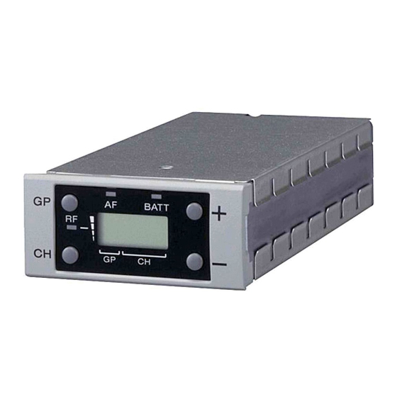
Block Diagrams 4-1. Circuit Description DP-476 Board The DP-476 board is composed of display block and WRU-806B is composed of RF-155 board and DP-476 operation control block. board. The display block has the LCD which indicates the various status of group and channels and the AF indicator LED, RF Board name Q’ty... -
Page 46: Cpu Pin Description
Clock terminal of IIC communication for EEPROM EEP_WP Write protection terminal of IIC communication for EEPROM . High: Impossible . Low: Possible Not used Not used Not used Not used Not used /RST 26, 27 LCD bias LCD bias LCD bias LCD bias Not used WRU-806B... - Page 47 RSSI level value of antenna A AF level value RSSI-B RSSI level value of antenna B MS_ADDR Master/Subordinate (sub) distinction A peculiar voltage to the slot of the tuner base unit is detected, and slot No. is distinguished. Avss WRU-806B...
-
Page 49: Overall Block Diagrams
R F B lock (B) AF (B) – 234.95MHz 10.7MHz CN301 FL101 Q101 SWF101 CF101 Q108 CF102 IC101 CF103 IC105 Ant. IN (4/4) Q102,103 IC203 RF Amp 1st Mixer SAWF 2nd Mixer Discriminator BPF(CF) IF Amp BPF(CF) IF Amp BPF(CF) WRU-806B... - Page 51 R127 R402 R493 X405 C301 C437 * D1 * B2 R494 * A1 X601 C302 C438 * A2 CF104 * B2 JC601 R128 R403 SUFFIX: -13 * A2 * D1 R404 R495 * B1 C303 C439 CF201 JC602 R129 WRU-806B...
- Page 53 COM0 COM1 COM1 COM2 COM2 COM3 COM3 SEG0 SEG1 SEG2 SEG3 ND801 SEG4 SEG5 COM1 COM2 SEG6 SEG7 SDG8 SEG9 SEG10 SEG11 SEG12 SEG13 SEG14 SEG15 SEG16 COM0 COM3 SEG17 SEG18 SEG19 GND_D DP-476 +3.3V GND_D BOARD NO. 1-885-695-13 WRU-806B...
- Page 54 L205 Q203 C258 C259 C238 C239 R252 1000pF 1000pF 3.3k R237 CF203 4.7uF 1000pF 1000pF 0.1uF 22uF 10uF 0.01uF 1.5k 0.01uF 100nH *L208 *L209 0.1uF 0.1uF 10.7MHz 6.3V 6.3V 3SK294(T5LSONY,F) 27nH 10nH IC203 LT5560EDD#TR RF-155 (1/3) BOARD NO. 1-885-697-13 WRU-806B...
- Page 55 *R480 *R482 *R490 *C470 *C456 0.1uF 0.1uF 100k 470k 0.1uF NJM2903V(TE2) R449 C428 R451 *C455 0.1uF 0.1uF 470k 0.1uF 100k D402 *D404 (3/3) (3/3) DA3S101F0L DA3S101F0L *IC410 IC408 NJM4558V-TE2 NJM2903V(TE2) No Mount for URX-M2 RF-155 (2/3) BOARD NO. 1-885-697-13 WRU-806B...
- Page 56 1608 C511 R512 C512 100uF 22uF 100uF R508 100uF 150k 6.3V 3216 RF-155 (3/3) C507 C506 C513 3225 0.1uF 0.1uF 100uF 6.3V C525 C504 C517 D501 D503 0.1uF RB161M-20TR BOARD NO. 1-885-697-13 100uF UMZ8.2T-T106 IC503 XC6365D103MR 3216 1608 GND_D WRU-806B...
- Page 58 Printed in Japan Sony Corporation 2012. 2 08 WRU-806B (U, CE) E 9-976-901-11 ©2012...
Need help?
Do you have a question about the WRU-806B and is the answer not in the manual?
Questions and answers