Table of Contents

Related Manuals for Sony WRR-855A


Summary of Contents for Sony WRR-855A
- Page 1 3-810-586-12(1) UHF Synthesized Tuner Unit Model: WRR-855A Operating Instructions Before operating the unit, please read this manual thoroughly and retain it for future reference. © 1995 by Sony Corporation [U64] [U66] [U68]...
-
Page 2: Table Of Contents
Overview ................3 Features ................ 3 unit. Record the serial number in the space provided below. System Configuration ..........4 Refer to these numbers whenever you call upon your Sony Parts Identification ............5 dealer regarding this product. WRR-855A ..............6 BTA-801 Portable Tuner Mount Adapter (Optional) .. -
Page 3: Overview
Overview The WRR-855A UHF Synthesized Tuner Unit in use with Versatile display an optional Portable Tuner Mount Adapter, such as the A variety of information is obtained at a glance on the BTA-801, provides a highly reliable portable diversity upper panel, such as the reception channel with the liquid-... -
Page 4: System Configuration
Overview System Configuration The WRR-855A can be used with the WRT-807A/810A/ 830A/867A UHF synthesized wireless microphone or WRT-808A/820A/822A/860A UHF synthesized transmitter. Sony 800 MHz band system models Frequency band Model name Transmitter or Model Frequency (MHz) Tuner channel microphone 770.125 - 775.875... -
Page 5: Parts Identification
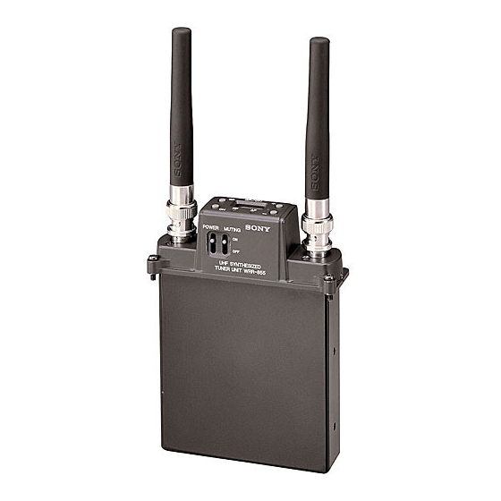
Parts Identification GP button CH button Liquid-crystal display WRR-855A + button – button BTA-801 Portable Tuner Mount Adapter (optional) ANT connectors !¡ AF indicator IN G M U T !™ P O W RF indicator O F F POWER switch... -
Page 6: Wrr-855A
See “Setting” on page 10. 4 Mounting screws Used to secure the WRR-855A to the BTA-801. 8 Liquid-crystal display For mounting, see “Mounting to a Portable Tuner Mount When you turn the power ON, the “HELLO” message Adapter”... -
Page 7: Bta-801 Portable Tuner Mount Adapter (Optional)
!¡ AF (audio frequency level) indicator !¢ Betacam attachment knob Lights when an audio signal greater than the reference level Used to fix the unit to a Betacam. is output. For attaching the unit to a Betacam, see page 24. !™... -
Page 8: Preparations
Mounting to a Portable Tuner Mount Adapter WRR-855A This section shows you how to moung the WRR-855A to the BTA-801 Portable Tuner Mount Adapter for example. By properly mounting the WRR-855A to the BTA-801 and attaching the two supplied antennas, a weatherproof structure is obtained. -
Page 9: Connecting The Power Cable
Connecting the Power Cable Attaching the Antennas Connect the DC 12 V IN connector of the BTA-801 to the Attach the supplied antennas to the two ANT connectors. DC OUT connector of a Betacam-series Camcorder using the DC power cable supplied with the BTA-801. BTA-801 (bottom) Match the connector pins with the inside of the... -
Page 10: Setting
Setting Operations Channel Selection Turn the POWER switch ON. Notes After the “HELLO” message, the tuner status shown Take the following precautions to prevent interference and before the tuner was previously turned OFF appears on noise. the display. • Do not simultaneously use two or more microphones and transmitters that are set to the same channel. - Page 11 Press the CH button when the desired group is displayed. Press the + or – button to select the group. The tuner goes to the channel selection mode and the Pressing the + button cyclically changes the groups in channel number flashes. the order of 00 to 11 to 12 to 13 to A1 to A2 to A3 to L1 to L2 to H1 to H2 and pressing the –...
- Page 12 Setting Distortion-check function After the desired channel is displayed, leave the unit for Before operating a wireless microphone or transmitter, you 5 seconds without pressing any buttons. can check for possible distortion by using the distortion- Channel selection mode is automatically canceled and check function of this unit.
-
Page 13: Mode
Setting and Releasing the T (Tone Squelch) OFF Mode The WRR-855A has the following three muting functions, Selecting the T OFF mode which work in combination. Turn the power ON while pressing and holding the GP and (1) Muting by RF input level: As sufficient S/N for the –... -
Page 14: Wireless Channel Selectable
To maintain this, Sony • If there is a TV broadcasting station nearby, to avoid recommends that one of the original Sony groups, number possible interference from its broadcast, do not use that 00, 11, 12, 13, A1, A2, A3, L1, L2, H1 or H2 is selected. -
Page 15: Wireless Channel Lists (1) - For 68-Version Model Using Tv Channels 68 And 69
Wireless Channel Lists (1) – For 68-Version Model Using TV Channels 68 and 69 Group 00: All channel access Use to scan for open channels. Use only for a one channel system. - Page 16 Wireless Channels Selectable Group 11: 11-channel group Group 12: 8-channel group Group 13: 8-channel group Use when both TV channels 68 and 69 Use when TV channel 69 is open. Use when TV channel 68 is open. are open. Group A3: 13-channel group Group A2: 13-channel group Group A1: 19-channel group The channels listed as Group A3 for...
- Page 17 Group L1: 7-channel Group L2: 7-channel Group H1: 7-channel Group H2: 7-channel group group group group Use when TV channel 68 is Use when TV channel 68 is Use when TV channel 69 is Use when TV channel 69 is open.
-
Page 18: Wireless Channel Lists (2) - For 66-Version Model Using Tv Channels 66 And 67
Wireless Channels Selectable Wireless Channel Lists (2) – For 66-Version Model Using TV Channels 66 and 67 Group 00: All channel access Use to scan for open channels. Use only for a one channel system. - Page 19 Group 11: 11-channel group Group 12: 8-channel group Group 13: 8-channel group Use when both TV channels 66 and 67 Use when TV channel 67 is open. Use when TV channel 66 is open. are open. Group A3: 13-channel group Group A2: 13-channel group Group A1: 19-channel group The channels listed as Group A3 for...
- Page 20 Wireless Channels Selectable Group L1: 7-channel Group L2: 7-channel Group H1: 7-channel Group H2: 7-channel group group group group Use when TV channel 66 is Use when TV channel 66 is Use when TV channel 67 is Use when TV channel 67 is open.
-
Page 21: Wireless Channel Lists (3) - For 64-Version Model Using Tv Channels 64 And 65
Wireless Channel Lists (3) – For 64-Version Model Using TV Channels 64 and 65 Group 00: All channel access Use to scan for open channels. Use only for a one channel system. - Page 22 Wireless Channels Selectable Group 11: 11-channel group Group 12: 8-channel group Group 13: 8-channel group Use when both TV channels 64 and 65 Use when TV channel 65 is open. Use when TV channel 64 is open. are open. Group A3: 13-channel group Group A2: 13-channel group Group A1: 19-channel group To simultaneously use up to 13...
- Page 23 Group L1: 7-channel Group L2: 7-channel Group H1: 7-channel Group H2: 7-channel group group group group Use when TV channel 64 is Use when TV channel 64 is Use when TV channel 65 is Use when TV channel 65 is open.
-
Page 24: Attaching And Connecting To A Betacam
Attaching and Connecting to a Betacam Use the Betacam attachment kit supplied with the BTA-801 Align the attachment plate of the back of the BTA-801 Portable Tuner Mount Adapter. with the holder and bracket. Attach the holder and bracket to the Betacam. Holder Binding head screws (M3×6) (2) Binding head screws... - Page 25 Connect the output cable (optional). THE SIZE R-8 55 UHF SYN UNI T WR TUN ER OUTPUT AUDIO IN Connect the DC power cable supplied with the BTA- 801. For the power cable connection, see page 9.
-
Page 26: Precautions
Precautions • On operation The tuner unit is precisely adjusted at the factory and no • The tuner unit must be used within the temperature range adjustment before use is necessary. Do not touch the of 0°C to 50°C (32°F to 122°F). Avoid using for an inside of the unit or try to repair it by yourself. -
Page 27: Messages On The Display
An error occurred in backup memory data. group/ channel selection and muting setting again. Err 02 The PLL synthesized circuit is in trouble. Contact your Sony dealer. The operating voltage exceeds the allowable Err 03 Contact your Sony dealer. value. -
Page 28: Specifications
EC-0.5C2 (XLR-3-11C type ↔ XLR-3-12C type) dBµ (A-weighted) 60 dB or more at RF input level 60 Design and specifications are subject to change without dBµ (A-weighted) notice.......................................... . 0 dBµ = 1 µV Sony Corporation Printed in Japan...
Need help?
Do you have a question about the WRR-855A and is the answer not in the manual?
Questions and answers