Table of Contents
Advertisement
Quick Links
Specifi cations
Power
24U =15-28 VAC/DC
12U =11.4-20 VAC/DC
Consumption
Relay (SDT) <20mA de-energized
<133mA energized
Solid State
<20mA de-energized
<90mA energized
Setpoint Ranges (DC) 2-20A, 10-50A, 20-100A
(AC) 2-17, 10-41, 20-80A
Setpoint Adjust
11 Turn potentiometer
Isolation Voltage
3KV
Frequency Range
DC to 400 Hz
Repeatability
0.5%
Hysteresis
5% of setpoint
Sensing Aperture
0.75" (19mm)
Case
UL 94-V0 Flammability Rated
Output Rating & Environmental
NOU
Isolated Solid State Switch
0.15A @ 240 VAC/DC
Off State Leakage
NONE
Operating Temp.
-20 to 50°C(-4 to 122°F)
Storage Temp.
-30 to 60°C (-22 to 140°F)
0-95% RH, Non Condensing
SDT
SPDT (Form C) Relay
5A General Purpose @ 240 VAC
5A @ 30 VDC
Operating and Storage -20 to 50°C (-4 to 122°F)
0-95% RH, Non Condensing
Approvals
UL/cUL, CE
For products intended for the EU market, the following is
applicable to the CE compliance of the product:
The DS3 series comply with EN 61010-1 CAT III 300Vrms
max. line-to-neutral measurement category. If insulated cable is
used for the primary circuit, the voltage rating of the measure-
ment category can be improved according to the insulation
characteristics given by the cable manufacturer.
Warning! Risk of Danger
Safe operation can only be guaranteed if the
current switch is used for the purpose it has
been designed for and within the limits of the
technical specifi cation. When this symbol is
used, it means you must consult all documen-
tation to understand the nature of potential
hazards and the action required to avoid them.
Warning! Risk of Shock
When operating the current switch, certain
parts of the module may carry hazardous live
voltage (e.g. primary conductor, controlled
load). The switch should not be put into op-
eration if the installation is not complete.
Model Number Key
DS3 - SDT - 24U
Power Supply
24U 24VAC/DC
12U 12VAC/DC
OUTPUT:
NOU Normally Open Solid State Switch, 0.15A
@ 240 VAC/VDC
SDT
Single Pole Double Throw (SPDT or
Form C) relay
SENSOR TYPE:
DS3 DC current sensing switch with 3 jumper selectable
range and adjustable setpoint
Ranges & Maximum Amps
RANGE
RANGE
MAX
CONTINUOUS
SOLID CORE
JUMPER
5 SEC.
LOW
2-20 A
No limit
MID
10-50 A
20-100 A
HIGH
Switching Response Time
ALL Ranges
ON Delay
80 ms max
5% over Setpoint
60 ms max
50% over Setpoint
60 ms max
100% over Setpoint
60 ms max
OFF Delay
3511 Charter Park Drive, San Jose, CA 95136
800-959-4014 or +1-408-871-7510 Phone
+1-408-871-7515 FAX
sales@nktechnologies.com, www.nktechnologies.com
INSTRUCTIONS
MAX
No limit
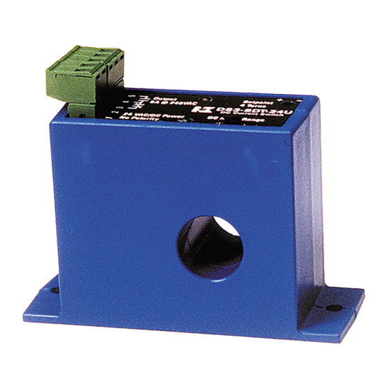
DC Current Operated Switch
Quick "How To" Guide
1. Run the wire you are monitoring through ap-
erture.
2. Mount the sensor.
3. Connect power & output wiring.
A. Make sure power supply matches specifi cations.
B. Make sure output load matches the output shown
on the sensors' label.
4. Adjust Setpoint
A. Chose correct range by positioning the Range
Jumper
B. Use the potentiometer to adjust the setpoint.
DS3 SERIES
DS3 Inst. Rev13, 08/18 P/N 393000103
Advertisement
Table of Contents

Related Manuals for NK TECHNOLOGIES DS3 Series


Summary of Contents for NK TECHNOLOGIES DS3 Series
- Page 1 UL/cUL, CE For products intended for the EU market, the following is applicable to the CE compliance of the product: The DS3 series comply with EN 61010-1 CAT III 300Vrms Switching Response Time max. line-to-neutral measurement category. If insulated cable is Quick “How To”...
- Page 2 Description Setpoint Adjustment DS3 Series are DC current operated switches. They operate Isolated Solid State Output Isolated Relay Output Range & Setpoint Power Supply (switch) when the current level through the hole exceeds the (Shown De-Energized) (Shown De-Energized) 12 or 24VAC/DC DS3 switches have two setpoint adjustment mechanisms: adjustable setpoint.
Need help?
Do you have a question about the DS3 Series and is the answer not in the manual?
Questions and answers