Table of Contents
Advertisement
Advertisement
Table of Contents

Related Manuals for Texecom Impaq S


Summary of Contents for Texecom Impaq S
- Page 1 Installation Manual Impaq S / Impaq SC INS877-1...
-
Page 2: Table Of Contents
Content 1.0 Introduction ..........................1.1 Impaq S ..........................1.2 Impaq SC ..........................2.0 Mounting ..........................2.1 Device mounting ......................... 2.2 Magnet mounting (type SC only) ..................3.0 Wiring configuration ......................3.1 End of Line (EOL) configuration ..................3.2 Connections ........................ -
Page 3: Introduction
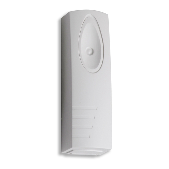
1.0 Introduction The Impaq S is a wired shock sensor and the Impaq SC is a wired shock sensor with the option for a magnetic contact. Sections 1.1 and 1.2 show the key parts of the devices. 1.1 Impaq S... - Page 4 INS877-1 4/20...
-
Page 5: Impaq Sc
Icon Item LED function select DIP switch Sensitivity selection button Alarm resistance value selection DIP switch Tamper resistance value selection DIP switch Input terminal block 1.2 Impaq SC INS877-1 5/20... - Page 6 INS877-1 6/20...
-
Page 7: Mounting
Icon Item LED function select DIP switch Sensitivity selection button Magnet sensor Alarm resistance value selection DIP switch Tamper resistance value selection DIP switch Input terminal block 2.0 Mounting 2.1 Device mounting Select the intended mounting position. The device can be installed in any mounting orientation. - Page 8 Figure 2 INS877-1 8/20...
- Page 9 Figure 3 INS877-1 9/20...
-
Page 10: Magnet Mounting (Type Sc Only)
2.2 Magnet mounting (type SC only) Once the device has been mounted, position the magnet so the notch is aligned with the arrow marker on the PCB. The magnet can be installed on either side of the device. Greater sensitivity is achieved by positioning the magnet so the notch is aligned with the arrow (see figure 4 for magnet distances). - Page 11 Approach Min Removal Max Axis (mm) (mm) Right INS877-1 11/20...
- Page 12 Left Once the correct position has been located fix the magnet in place (see figure 5) Figure 5 INS877-1 12/20...
-
Page 13: Wiring Configuration
3.0 Wiring configuration INS877-1 13/20... -
Page 14: End Of Line (Eol) Configuration
This table is for the shock sensor only Cooper Panel Support Texecom Honeywell DSC Menvier Alarm EOL Tamper EOL Select the correct resistance value for Tamper and Alarm by moving the DIP switch to the ON position (Texecom values shown in example below). INS877-1 14/20... - Page 15 NOTE: The product will only function if both DIP switches have a single switch set to the ON position. If no switches or multiple switches are moved the product will not function as expected. INS877-1 15/20...
-
Page 16: Connections
3.2 Connections Connect two wires into the 0V and 12V terminals to supply power to the device from an EN50131 compliant power supply unit. Connect two wires into the terminals marked EOL for the Alarm and Tamper signals. These wires should be terminated into a zone on the intruder panel. 3.3 Connections - Impaq SC only Connect two cores into the terminals marked MAG for the alarm signals from the magnetic contact. -
Page 17: Setting The Shock Sensitivity
NOTE: Any selections made on the comfort and detection LED switches will be overridden when the RLED function is utilised. 5.0 Setting the shock sensitivity After powering up the device single press the sensitivity button and the LED will flash blue defaulting to sensitivity setting 2. There are 5 sensitivity settings from 1 to 5 with 1 being the least sensitive (slowest flash rate) and 5 the most sensitive. -
Page 18: Specifications
Recommended Sensitivity Setting* Material Radius Wood Framed Glass Window Concrete 0.5m Before testing the device, press and hold the button (3 secs) to set the desired sensitivity setting. The LED will turn green for confirmation at which point the device is ready for impact testing. -
Page 19: Legal Information
As the Impaq S/SC is not a complete alarm system, but only a part thereof, Texecom cannot accept responsibility or liability for any damages whatsoever based on a claim that the Impaq S/SC failed to function correctly. Due to our policy of continuous improvement Texecom reserves the right to change specification without prior notice. - Page 20 Certified by Telefication B.V. INS877-1 20/20...
Need help?
Do you have a question about the Impaq S and is the answer not in the manual?
Questions and answers