Table of Contents
Advertisement
Quick Links
WARNINGS
• TO AVOID FIRE, SHOCK, OR DEATH, TURN OFF ALL POWER SERVICING THE DEVICE, TEST THAT POWER IS
OFF BEFORE SERVICING OR WIRING and ensure connections are made in the same sequence as existing device
connections.
• This equipment MUST BE installed and serviced by a qualified electrician.
• Leviton circuit breakers MUST BE used with a Leviton circuit breaker enclosure.
• Before providing power to the load center, check all electrical connections and confirm that the wiring is correct.
• Replace all doors and covers before connecting power to this equipment.
Installation
1.
Remove Compartment Covers
a.
3.
Remove the Load Center Door (Optional)
The load center door can be removed for easier installation.
NOTE: When installation is complete, align the door hinge with
the hinge pin and insert downward until door is seated.
a.
5.
Remove Knockouts for Bottom Feed Wiring
NOTE: For top feed wiring, use the overhead tunnel accessory and follow the instructions
(sold separately).
NOTE: Before removing any knockouts from the enclosure, consult the local electrical code to
determine the knockout requirements.
a.
b.
Strike the center of
Pry each ring up one at a
the knockout.
time with a pair of pliers.
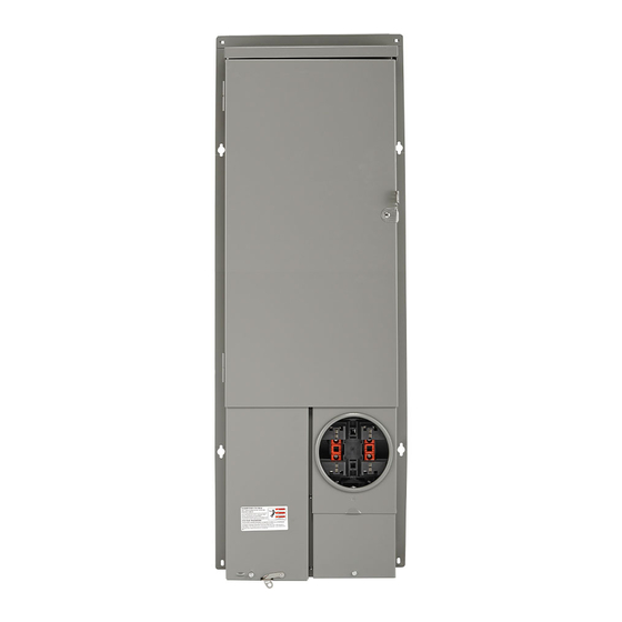
Combination Service Entrance Device (CSED)
Cat Nos. LPxxx-SRL, LPxxx-SR
INSTALLATION INSTRUCTIONS
b.
b.
c.
Grip both ends with the pliers
to bend the rings until they
disconnect from the enclosure.
Solar-ready
CAUTIONS
• Use ONLY approved fittings and clamps to avoid damage to wires.
• Ensure that all branch circuit breakers are in the OFF position before installing into the panel.
• To be installed and/or used in accordance with electrical codes and regulations.
2.
Install 5th Jaw Application (Optional)
NOTE: The wire retention channel can be used to ensure wire stays in place.
a.
4.
Mount the Enclosure
This panel series can only be mounted in a semi-flush manner. Consult the local electrical
code to determine the proper installation height. The right side of the panel has a meter socket
centerline marking that can be referenced to achieve the proper installation height.
To mount the unit, use the mounting brackets on the left and right outside perimeter of the panel.
Use outdoor approved screws or nails (not provided) in the mounting brackets to secure the
enclosure to the wall studs.
Mount a minimum of 12 inches away from an adjacent wall to the right side of the panel to allow
ample room for accessing the door latch.
NOTE: Install unit within rough opening of dwelling and seal off all gaps around the flange and
enclosure body to the rough opening in the wall. Apply a minimum 1 inch overlap of all-weather
flashing tape, or equivalent over mounting flanges.
NOTE: -SRL models suitable only for use as service equipment. Install no more than six main
disconnecting means.
6.
Connect to Phase, Neutral and Ground Conductors
CAUTION: Use ONLY approved fittings and clamps to avoid damage to wires.
a.
Bring the phase, neutral and ground conductors into the enclosure's service chamber.
b.
Connect the phase, neutral and ground conductors to the appropriate terminals and
torque to spec. You may reference the wire terminal table inside the panel door.
PHASE
NEUTRAL
GROUND
c.
b.
Connect to the neutral bar using
the opening next to the ground
lug in the service chamber.
PK-A3305-10-00-5A
ENGLISH
Advertisement
Table of Contents

Related Manuals for Leviton LP-SRL Series


Summary of Contents for Leviton LP-SRL Series
- Page 1 • This equipment MUST BE installed and serviced by a qualified electrician. • Leviton circuit breakers MUST BE used with a Leviton circuit breaker enclosure. • Before providing power to the load center, check all electrical connections and confirm that the wiring is correct.
- Page 2 LIMITED PRODUCT WARRANTY For Leviton’s limited warranty, go to www.leviton.com. For a printed copy of the warranty you may call 1-800-323-8920 or write to Leviton Manufacturing Co., Inc., Att: Customer Service Dept., 201 North Service Road, Melville, New York 11747.
Need help?
Do you have a question about the LP-SRL Series and is the answer not in the manual?
Questions and answers