Table of Contents
Advertisement
Available languages
Available languages
Quick Links
MU 03.03.mmm REV.1
Via del Lavoro, 80 - 40056 CRESPELLANO (Bologna) ITALY -
P.O. BOX, 150 - 40011 ANZOLA EMILIA (Bologna) - ITALY
MANUALE DI ISTRUZIONI
REGOLATORE ELETTRONICO tipo MPR
INSTRUCTION MANUAL
ELECTRONIC POWER FACTOR REGULATOR type MPR
MANUEL D'INSTRUCTIONS
REGULATEURS AUTOMATIQUES DE PUISSANCE REACTIVE type MPR
MANUAL DE INSTRUCCIONES
REGULADOR ELECTRÓNICO DE POTENCIA REACTIVA tipo MPR
• ITALIANO
Power Factor Regulator
cos Φ Φ Φ Φ V
A
°C
1 2 3 4 5 6
Select
_
C/K
PF
Prog.
made in Italy
+39 051/733.383 - Fax. +39 051/733.620
7 8
+
MPR8
09/01
Advertisement
Table of Contents

Subscribe to Our Youtube Channel
Related Manuals for Comar Condensatori MPR


Summary of Contents for Comar Condensatori MPR
- Page 1 MPR8 made in Italy MANUALE DI ISTRUZIONI REGOLATORE ELETTRONICO tipo MPR INSTRUCTION MANUAL ELECTRONIC POWER FACTOR REGULATOR type MPR MANUEL D’INSTRUCTIONS REGULATEURS AUTOMATIQUES DE PUISSANCE REACTIVE type MPR MANUAL DE INSTRUCCIONES REGULADOR ELECTRÓNICO DE POTENCIA REACTIVA tipo MPR • ITALIANO...
- Page 2 1.PRESENTAZIONE.................……….. pag. 3 2. SCELTA del TRASFORMATORE AMPEROMETRICO (T.A.)..…..pag. 3 3. ISTRUZIONI d’USO…................pag. 4 COLLEGAMENTI ELETTRICI “ FISSAGGIO MECCANICO “ POTENZA delle BATTERIE “ NUMERO dei GRADINI “ 4. FUNZIONAMENTO AUTOMATICO / MANUALE.......…..pag. 5 5. VISUALIZZAZIONI................... pag. 5 6.
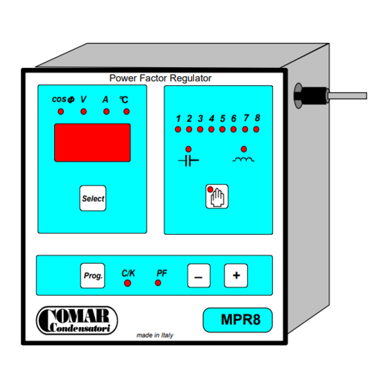
- Page 3 Sensore esterno di temperatura Power Factor Regulator Led indicazione cos Φ Φ Φ Φ V grandezza visualizzata ° C Led visualizzazione 1 2 3 4 5 6 batterie inserite Display digitale Led INDUTTIVO inserzione batterie Selezione Led CAPACITIVO visualizzazione display Select disinserzione batt.
- Page 4 3. ISTRUZIONI d’ USO COLLEGAMENTI ELETTRICI: eseguibili mediante morsettiera femmina a vite, ad inserzione obbligata per cavi 2,5mm max., posta nella parte inferiore del regolatore. Fig.1 Schema di collegamento • Per consentire un corretto funzionamento é indispensabile rispettare il collegamento del T.A. (fase R a monte dei condensatori di rifasamento) e del...
-
Page 5: Funzionamento
4. FUNZIONAMENTO Premendo il pulsante rappresentato dalla serigrafia , si commuta il funzionamento da AUTOMATICO (di default all’accensione) a MANUALE e viceversa. • AUTOMATICO: condizione di funzionamento standard all'accensione. Quando vi sono dei carichi induttivi inseriti (motori, trasformatori, lampade a scarica, ecc.), si accende il led rosso _∩∩∩_ ed il regolatore comanda l'inserzione delle batterie di condensatori necessarie. - Page 6 TABELLA DEI VALORI C/K per corrente media sul circuito amperometrico pari a 2,5A C = Potenza 1 a batteria in Kvar (400Vac) 12,5 Commento [B1]: Pagina: 4 T.A. 30/5 50/5 60/5 80/5 100/5 150/5 200/5 250/5 300/5 400/5 500/5 600/5 800/5 1000/5 1200/5...
- Page 7 • • • • Allarme per mancato rifasamento: ogni condizione che impedisce il raggiungimento temporaneo del cosfì medio impostato entro il tempo di 15 minuti, causa l'allarme per mancato rifasamento. Tale stato determina: la visualizzazione automatica della misura di cosfì e del relativo led (cosϕ) lampeggianti e la chiusura del contatto di allarme facente capo ai morsetti X1-X2.
-
Page 8: Dati Tecnici
8. ANOMALIE di FUNZIONAMENTO e loro RIMEDI Le cause di mancato od errato funzionamento sono, quasi sempre, riconducibili ad errori di collegamento. PROBLEMA SOLUZIONE Inserzione di tutte le batterie con Il T.A. e' a monte dei carichi ma non dei condensatori. pochi carichi funzionanti Collegarlo come da schema (v. -
Page 9: Garanzia Sul Prodotto
GARANZIA SUL PRODOTTO La COMAR Condensatori S.p.A. garantisce i propri prodotti per un periodo di 12 mesi dalla data d'acquisto. La garanzia copre i difetti dei materiali e di fabbricazione ed è da intendere per merce resa franco Ns. fabbrica. -
Page 10: Main Features
It needs to pass through the hole of the C.T. all the derived cables. Note. MPR regulators are able to detect automatically the current phasing of the CT. It is not necessary to ensure correct polarity connections as with other Power Factor Regulators. -
Page 11: Instruction For The Use
3. INSTRUCTION for the USE 3.1 ELECTRICAL CONNECTION : by means of plug connector with terminal fixing screws for the cable have to be of 2,5mm section, mounted in the base of the regulator. Fig. 1 The external connection • It is very important to ensure correct connection of the CT (in L1 phase upstream... -
Page 12: Digital Display
4. WORKING SITUATION The AUTOMATIC (default condition when switching on the regulator) or MANUAL working condition are obtained by pushing the button • AUTOMATIC working This is the standard condition when switching on the regulator. When the network is inductive (motors, transformers, fluorescent lamps, etc.), the red led _∩∩∩_ is on and the regulator begins to connect capacitors banks. - Page 13 TABLE for medium current values of 2,5 Amps C = First bank power expressed in kvar (400V) 12,5 Commento [B2]: Pagina: 4 T.A. 30/5 50/5 60/5 80/5 100/5 150/5 200/5 250/5 300/5 400/5 500/5 600/5 800/5 1000/5 1200/5 1500/5 2000/5 2500/5 3000/5 4000/5...
-
Page 14: Reset Procedure
The MPR has a normally closed N/C alarm contact (rated 5 A 250 V resistive load). It will be possible to give an external alarm signal. This contact is signed with X1 and X2 (ALARM) in the base of the regulator. -
Page 15: Technical Data
TROUBLE SOLUTION All banks on with a low inductive load on The CT is connected upstream the load but not of capacitors. the network Connect the CT as shown in the connection diagram The C/K value is not correct. Check in the table "C/K VALUES" for the right value Continuous switching on and off of first The power of the first bank is too high for the selected PF requirements bank (hunting phenomena) -
Page 16: Warranty
Comar Condensatori S.p.A. are not liable for direct or indirect damages consequent the missing or the incorrect operation. In any case and for any reason COMAR Condensatori S.p.A. can not be considered liable for possible direct or indirect damages, consequent the malfunctioning of P.F.Corrector, caused from mistakes of assembly or from inadequate use of the same. -
Page 17: Instruction D'emploi
Sonde externe de température Power Factor Regulator Led indication Φ Φ Φ Φ V grandeur visualisée ° C 1 2 3 4 5 6 Led visualisation batteries insertées Display digital Led INDUCTIF insertion batteries Sélection visualisation display Led CAPACITIF Select désinsertion batteries Sortie programmation Sélecteur fonctionnement... -
Page 18: Connexions Electriques
CONNEXIONS ELECTRIQUES: le bornier de connexion à insertion obligée est monté à l’arrière dans la partie en basse du régulateur et accepte des câbles jusqu’à 2,5mm Fig.1: Connexions électriques du régulateur • Il est indispensable de respecter le branchement du TI (phase L1 en amont des condensateurs de compensation) et du... - Page 19 Le bouton permet de commuter du mode MANUEL au mode AUTOMATIQUE. • AUTOMATIQUE: á partir du moment où les charges inductives (moteurs, transformateurs, lampes à décharge, etc.) deviennent effectives la led rouge indiquant _∩∩∩_ s’allume et le régulateur commande l’insertion de la batterie nécessaire à la compensation. Si un excès de puissance capacitive est créé, la led indiquant –³³–...
- Page 20 12,5 Commento [B3]: Pagina: 4 T.A. 30/5 50/5 60/5 80/5 100/5 150/5 200/5 250/5 300/5 400/5 500/5 600/5 800/5 1000/5 1200/5 1500/5 2000/5 2500/5 3000/5 4000/5 5000/5 1000 • Pour les intensités moyennes sur les circuits ampéremètriques (secondaire du T.I.) inférieures à 2A, réglez à la valeur supérieure de C/K.
- Page 21 L’afficheur cosinusϕ continuera de clignoter afin de signaler l’intervention. Pour annuler la mémoire d’alarme, effectuez la procédure de “RESET” (voir § 7.7 procédure de Reset). Alarme de tension: une tension d'alimentation supérieure à 110% de la tension nominale pendant plus de 10 secondes déclenche une alarme “Tension max.”.
-
Page 22: Données Techniques
8. ANOMALIES de FONCTIONNEMENT et REMEDES Les causes de disfonctionnement sont essentiellement dues à des fautes de raccordement. PROBLEMES SOLUTIONS Enclenchement de tous les gradins avec Le T.I. est en amont des charges et non des condensateurs. peu de charges inductives Branchez selon le schéma (voir §... -
Page 23: Garantie
La garantie se borne au remplacement du matériel défectueux. En aucun cas et où que ce soit, la société COMAR Condensatori ne peut être rendue responsable d’éventuels dommages directs ou indirects résultant d’une mauvaise installation, d’un mauvais montage ou d’un usage inadapté... - Page 24 Sensor externo temperatura Power Factor Regulator Φ Φ Φ Φ ° C 1 2 3 4 5 6 Display medidas Leds escalones insertados Leds IND/CAP Select Seleccion medidas Selector AUTO / MAN Prog. Selector programa Regulacion Pulsador Reset MPR8 C/K y COS FI made in Italy "+"...
-
Page 25: Instrucciones De Uso
3. INSTRUCCIONES de USO 3.1 CONEXIONADO ELÉCTRICO : mediante un regletero hembra a tornillo de posición de inserción obligada en la parte inferior del regulador. Fig.1 Esquema de conexionado • Es indispensable respetar el conexionado del TA (fase R antes de la batería de condensadores) y de la señal de tensión (fase... -
Page 26: Indicador Digital
4. FUNCIONAMIENTO El funcionamiento automático o MANUAL es obtenido apretando el pulsador • Funcionamiento AUTOMÁTICO Condición de funcionamiento standard al conectarse. Cuando hay cargas inductivas conectadas (motores, transformadores, lamparas de descarga) se enciende el led rojo _∩∩∩_ y el regulador comanda la inserción de los escalones necesarios. - Page 27 TABLA de los VALORES C/K (para corriente media cerca 2,5A) C = Potencia 1° escalón en kvar (400V) 12,5 Commento [B4]: Pagina: 4 T.A. 30/5 50/5 60/5 80/5 100/5 150/5 200/5 250/5 300/5 400/5 500/5 600/5 800/5 1000/5 1200/5 1500/5 2000/5 2500/5 3000/5...
- Page 28 Para anular el estado de alarma actuar el procedimiento de RESET . • Alarma de temperatura (solo MPR 8) El control de la temperatura se efectúa mediante una sonda externa. La sonda debe ser conectada o desconectada con el regulador desconectado (ver panel frontal) =Primer umbral 35 ºC.
-
Page 29: Datos Técnicos
8. ANOMALÍA de FUNCIONAMIENTO y SOLUCIONES a los mismos la causa de un eventual defectuoso funcionamiento son debidos casi siempre ha errores de conexionado. PROBLEMA SOLUCIÓN Inserción de todos los escalones con El TA esta antes de las cargas pero no de los condensadores. poca carga insertada Conectarlo según el esquema. -
Page 30: Advertencia General
10. GARANTÍA, ADVERTENCIA y RESPONSABILIDAD GARANTÍA SOBRE EL PRODUCTO La COMAR Condensatori S.p.A. garantiza el propio producto por un periodo de doce meses de la fecha de adquisición. La garantía cubre el defecto de material y de fabricación se ha de entender para entrega mercancía franco Ns. - Page 31 COMAR CONDENSATORI S.p.A. Via del Lavoro, 80 - 40056 CRESPELLANO (Bologna) ITALY +39 051 733.383 - Fax. +39 051 733.620 P.O. BOX., 150 - 40011 ANZOLA EMILIA (Bologna) ITALY...
Need help?
Do you have a question about the MPR and is the answer not in the manual?
Questions and answers