
Summary of Contents for BAS LC-4C
- Page 1 (217) 352-9330 | Click HERE Find the Bioanalytical Systems LC-4C at our website:...
- Page 2 LC-4C March, 2000 MF-9081 INSTRUCTION MANUAL Electrochemical Detector B i o a n a l y t i c a l S y s t e m s , I n c 2 7 0 1 Ke n t Ave n u e...
- Page 3 Never touch the electrochemical cell, the cell wires, or any part of the cell while the detector is operating. Before touching the cell, make sure that the cell switch on the front panel of the LC-4C amperometric controller is in the “STANDBY” or “OFF” positions. Do not operate cell while dry, or without connection to the reference electrode.
-
Page 4: Table Of Contents
3.5 Arrangement of Components and Connections ............12 3.6 Chromatography Connections................. 15 Section 4. Operating the Electrochemical Detector ..............23 4.1 LC-4C Front Panel ....................23 4.2 LC-4C Rear Panel....................27 4.3 CC-5 Rear Panel...................... 31 4.4 Routine Operating Procedure .................. 32 Section 5. - Page 5 Table of Contents Artisan Technology Group - Quality Instrumentation ... Guaranteed | (888) 88-SOURCE | www.artisantg.com...
-
Page 6: Section 1. Preface
To use this detector, you will require a liquid chromatograph, a data recording device, and appropriate end-fittings and tubing for the connection between column and detector. The LC- 4C is a component of the LC-44 detector and the modular BAS 480 series of liquid chroma- tographs. - Page 7 Several accessories may be added by the user or by service personnel at a later date: The LC-4C Dual CELL LEADS (EW-8114) provide the additional cable to transform an ex- isting single-electrode detector into true dual-electrode operation. A second LC-4C controller (or an LC-3C/D/E Petit Ampère) must also be purchased.
-
Page 8: Section 2. Support Policy
For any product expressly covered under this warranty, BAS is liable only to the extent of re- placement of defective items. Bioanalytical Systems, Inc. shall not be liable for any personal injury, property damage, or consequential damages of any kind whatsoever. -
Page 9: Service Information
Section 2. Support Policy Bioanalytical Systems provides a skilled service staff available to solve your technical prob- 2.4 Service Information lems if an equipment-oriented problem should arise. For further details, call customer serv- ice personnel (1-800-845-4246), who will route your problem to the correct individual. Fol- lowing discussion of your specific difficulties, an appropriate course of action will be de- scribed and the problem resolved accordingly. -
Page 10: Section 3. Installation
(see Section 2). Figures 3.1–3.4 show the various components of the complete system. Figure 3.1. Top view of CC-5 flowcell configured as part of a BAS 480 system. Refer to Table 3.1 for descriptions. PREHEATER POWER HIGH Artisan Technology Group - Quality Instrumentation ... Guaranteed | (888) 88-SOURCE | www.artisantg.com... - Page 11 Inlet Tubing, Stainless Steel (for preheater) or Teflon (without preheater, #17) Analytical Column, 100 × 3.0 mm, 3 µm ODS (BAS P/N MF-8954) (not provided if only detector is purchased) Column End Fittings (not provided with detector purchases, BAS 480 ONLY) Connecting Tube from PM-80 Pump to Injection Valve (when installed) PTFE Outlet Tubing (0.5-mm i.d.) (note the small piece of larger tubing located midway on the tube, used to secure the...
- Page 12 TO PREVENT ELECTRICAL SHOCK, DO NOT REMOVE COVER. NO USER SERVICEABLE PARTS INSIDE. REFER SERVICING TO FACTORY PERSONNEL. LC-44 SERIES BAS 480 ANALYZER CONNECT ONLY TO "HEATER MADE IN USA OUTLET" ON BAS LC-22C CONNECT ONLY TO "LC-23C PROBE" ON BAS LC-22C REMOTE OUTPUT APP E...
- Page 13 Section 3. Installation Figure 3.4. BAS 480 Liquid Chromatograph with PM-80 Pump at bottom level. The column and injection valve are mounted in the detector compartment at the top level. Refer to Table 3.1 for descriptions of numbered components. DISPLAY...
-
Page 14: Power Requirements
Section 3. Installation The LC-4C and (optional) LC-22C instruments are operated with either 100, 120, 220, or 3.2 Power Requirements 240 V AC and 50 or 60 Hz power, but the correct voltage must be selected at the cord con- nector before use. -
Page 15: Local Environment
Section 3. Installation Amperometric detection is a highly sensitive technique. The currents measured typically fall 3.3 Local Environment in the picoampere or nanoampere range. Hence, smooth operation can easily be influenced by electrical disturbances in the environment. Also, since detection is due to a chemical re- action, its response (and baseline drift) is temperature-dependent;... -
Page 16: Solvent Delivery Requirements
Ideally, this instrument will be part of a BAS 480 Liquid Chromatograph. The BAS PM-80 Pump in this system provides excellent flow-rate precision and minimal pump pulsation. The PM-80 Pump may be connected di- rectly to the injection valve port (see #26 in Figure 3.1). -
Page 17: Arrangement Of Components And Connections
Section 3. Installation NOTE: Should you be installing as retrofits either the LC-4C Dual Upgrade Kit or the CC-5 3.5 Arrangement of Components and Preheater Module, refer to the installation instructions in Section 5 or Section 6.2, respec- Connections tively. The instructions below are for startup in a new installation. - Page 18 ADDRESS OUTPUT LC-22C Made in USA Figure 3.9. Connection of leads to LC-4C(s) for single (left) and dual (right) operation. CAUTION: CAUTION: TO PREVENT ELECTRICAL SHOCK, DO NOT REMOVE TO PREVENT ELECTRICAL SHOCK, DO NOT REMOVE COVER. NO USER SERVICEABLE PARTS INSIDE.
- Page 19 NOTE: If you have an integrator or data station with wide dynamic range, match the output of the LC-4C to the input range of your data device. The LC-4C has both 1 V and 10 mV outputs, making it compatible with the majority of popular chart recorders, integrators and workstations.
-
Page 20: Chromatography Connections
5 chassis along the sides and back provide tubing access, no matter what the orienta- tion. On a BAS 480 system, the detector components may sit directly on top of the PM-80 Pump. See Figures 3.2–3.4 and 3.7 for ideas. - Page 21 Section 3. Installation While the column is equilibrating, remove the three reference electrodes from the detector accessories package. Follow diagrams in the enclosed Electrode Manual for removal of the protective sheath used in packaging and shipping. Soak all reference electrodes in a 3 M sodium chloride solution, in a setup which KEEPS THE CONNECTING PIN DRY.
- Page 22 Section 3. Installation Figure 3.11. Correct alignment of Teflon tubing in fingertight fittings. CORRECT WRONG (DEAD VOLUME) Systems WITHOUT CC-5 Preheater Module: Connect the TEFLON detector inlet tube di- rectly to the column outlet. Then connect the detector outlet tube to the auxiliary elec- trode block.
- Page 23 Section 3. Installation Place a 0.002"-thick TG-2M cell gasket (MF-1046) over the two registration pins on the steel auxiliary electrode block, keeping the long axis of the cut-out in a horizontal ori- entation. Align the WORKING ELECTRODE BLOCK in the configuration desired. Note the orientation of the dual electrodes in relation to the flow through the thin-layer cell (Figure 3.12).
- Page 24 Section 3. Installation 10. Remove one of the reference electrodes from the sodium chloride solution and assemble with the retainer and O-ring as shown in Figure 3.13. Figure 3.13. Exploded and assembled views of reference electrode components. REFERENCE ELECTRODE RETAINER REFERENCE ELECTRODE REFERENCE...
- Page 25 Section 3. Installation 14. While the power to the LC-4C controller is still OFF, make electrical connections to the working electrode controlled by a SINGLE LC-4C as follows: White connector (socket): to reference electrode pin Black connector (W1 pin): to working electrode socket...
- Page 26 Section 3. Installation 16. Dual-Electrode Operation: Customers with a single LC-4C detector can operate the generator and working elec- trodes at independent applied potentials (QUASI-DUAL mode). Only the working elec- trode produces a high-quality filtered output. Customers with two LC-4C detectors can operate two working electrodes, each producing high-quality filtered output (DUAL mode).
- Page 27 At the other end of the DUAL electrode cable are two special connectors that plug into the CELL socket on the back of the LC-4C detectors. The longer of these leads controls W2, and the shorter controls W1. Make sure that the internal pins of these connectors are prop- erly aligned before plugging in.
-
Page 28: Section 4. Operating The Electrochemical Detector
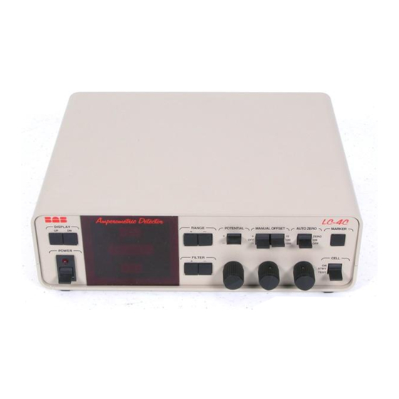
Section 4. Operating the Electrochemical Detector Section 4. Operating the Electrochemical Detector This section describes each feature of the LC-4C’s front panel (Figure 4.1). 4.1 LC-4C Front Panel Figure 4.1. Front panel of LC-4C detector controller. DISPLAY RANGE POTENTIAL MANUAL OFFSET... - Page 29 Section 4. Operating the Electrochemical Detector RANGE The RANGE keys set the controller output (gain) range. Preprogrammed ranges are selected by pressing the [+] and [–] keys and observing the display. Ranges from 0.1 nAfs (nanoamps per full-scale pen deflection) to 50 µAfs are provided in 18 steps. For example, a setting of 10 nAfs indicates that an output signal of 5 nanoamps would produce a pen de- flection of one-half full scale.
- Page 30 1) the baseline on your integrator is zero or negative, or 2) your chart-recorder pen does not go to the “zero” position when the LC-4C output display reads zero. To use this control, zero both the LC-4C and the recording device independently, then turn the con- trol knob until the baseline on the recording device is at the desired location.
- Page 31 Section 4. Operating the Electrochemical Detector FILTER This control adjusts the cutoff frequency of the active 4-pole Bessel filter. Filter settings be- tween 0.02 and 1.0 Hz (in 14 steps) may be selected by pressing the [+] and [–] keys. The filter setting selected is shown on the display.
-
Page 32: Lc-4C Rear Panel
These three banana-jack terminals (to the right of the OXD/RDN switch) feed the analog out- put from the LC-4C to a recording device. The output signal is a voltage corresponding to the amount of current produced at the working electrode. Two output voltages are provided. - Page 33 Section 4. Operating the Electrochemical Detector TERMINAL STRIP A 16-connector terminal strip allows connections for the following functions: REMOTE Connections here allow remote REZERO (AUTO-ZERO) and MARK (CHART MARK). The functions operate identically to those on the front panel, but are initiated by a switch closure to ground, or a low level TTL signal, from a remote instrument such as an autosampler or integrator.
- Page 34 RANGE control. The factory-set default gain range is 0.5 µAfs. You may want to reset this default to the gain at which you typically work. Then the LC-4C will automatically re-equilibrate after a power outage. Dip switch positions are as follows:...
- Page 35 PC remote Remote enabled Remote disabled NOTE: Enabling PC remote does not put the LC-4C in REMOTE, but allows the PC interface to control REMOTE/LOCAL operation. Artisan Technology Group - Quality Instrumentation ... Guaranteed | (888) 88-SOURCE | www.artisantg.com...
-
Page 36: Rear Panel
REFER SERVICING TO FACTORY PERSONNEL. LC-44 SERIES BAS 480 ANALYZER CONNECT ONLY TO "HEATER MADE IN USA OUTLET" ON BAS LC-22C CONNECT ONLY TO "LC-23C PROBE" ON BAS LC-22C CELL LEAD The mounting bracket on either the single- or dual-electrode cable mounts to the rear panel with two 6-32 screws. -
Page 37: Routine Operating Procedure
Normal Startup Procedure WARNING: The CELL switch must be in the STBY position when the LC-4C is turned on or off, and for any electrode servicing. Disassembling a “live” cell can permanently damage the working electrode and the electronic circuits. - Page 38 Section 4. Operating the Electrochemical Detector 11. If you are sure all cell leads are connected, turn the CELL switch to ON. 12. When the electrode is first turned on, you should see a large current signal. This is the “charging and transient background current”...
- Page 39 Section 4. Operating the Electrochemical Detector Artisan Technology Group - Quality Instrumentation ... Guaranteed | (888) 88-SOURCE | www.artisantg.com...
-
Page 40: Section 5. Upgrading To A Dual Amperometric Detector
LC-4C detector (see Section 3.6, #16). Each LC-4C controls its assigned working electrode independently, in terms of both potential control and current amplification. The upgrade requires only an LC-4C controller (or an LC-3C/D/E Petit Ampère) and a dual- cell lead (EW-8114). To set up for dual operation: Turn off power to the detector and disconnect the cell leads from the transducer. - Page 41 W1 and W2 controllers in a master/slave relationship. For W2 to operate, W1 must be active first. You may elect to operate W1 by itself, as you would with a single LC-4C. That is permissible; the second LC-4C need not be powered. The reverse mode is not possible, however.
-
Page 42: Section 6. Temperature-Stabilized Detector Operation
Section 6. Temperature-Stabilized Detector Operation Section 6. Temperature-Stabilized Detector Operation Thermostatted control of the effluent temperature before it reaches the cell reduces the ef- 6.1 Rationale for Use fects of ambient temperature change on electrochemical detection. Furthermore, temperature control of the column protects the separation from the effects of temperature change, and when the LC-23C cartridge column heater is used with the CC-5 detector package, the dis- tance between the heated column and cell inlet is quite small and there will be sufficient tem- perature control to minimize effects on detection. - Page 43 Section 6. Temperature-Stabilized Detector Operation For water, the reaction is sluggish at moderate potentials; this is due to poor heterogeneous electron transfer kinetics at the electrode surface. Elevations in temperature increase the het- erogeneous rate constants, and the background current (the measure of the rate of electron transfer) correspondingly increases.
-
Page 44: Installation Of Detector Preheater Module On Cc-5
Section 6. Temperature-Stabilized Detector Operation Cell temperature control is an option on all BAS CC-5 series detectors. It may be factory-in- stalled or placed in service by the user in just a few minutes. The Preheater Module is shown schematically in Figure 6.2. A retractable core intimately contacts 2 to 3 turns of cap- illary tubing for thermal equilibration;... - Page 45 Capillary tubing is supplied for maximum flexibility. Place the LC-22C Temperature Controller directly under the LC-4C controller(s), per Fig- ure 6.3. Brackets are available to secure the temperature controller, LC-4C and CC-5 together for increased stability. See Section 3.5 #5 for details. Make electrical connections: Insert the red, yellow and black plugs into the color-matched jacks on the LC-22C Temperature Controller labeled PROBE 1 or PROBE 2.
-
Page 46: Appendix I. Electronic Troubleshooting
It may take 10 to 15 seconds for the voltmeter reading to stabilize when switching between certain ranges, due to the influence of the active filter on the LC-4C. This is normal! Artisan Technology Group - Quality Instrumentation ... Guaranteed | (888) 88-SOURCE | www.artisantg.com... - Page 47 10. Flip the MANUAL OFFSET polarity to [+]. Change the display to Offset . Turn the OFF- SET control knob until a reading of 10 nA is shown on the LC-4C display. The output reading on the voltmeter should be 0 V ± 150 mV. Switch the OFFSET polarity to [–] while leaving the POTENTIAL polarity at [+].
-
Page 48: Appendix Ii. Operation Of The Lc-4Ce
Appendix II. Operation of the LC-4CE Appendix II. Operation of the LC-4CE The LC-4CE is a modification of the standard LC-4C. Two circuit elements have been added to better meet the requirements of capillary electrophoresis: A clamp circuit, to protect the LC-4C electronics if the high voltage ground is lost. - Page 49 Appendix II. Operation of the LC-4CE Waveform Generator Circuit The waveform generator provides a bipolar square wave centered at 0 V. There are four con- trols associated with the waveform generator: Clean (on back panel) Clean adj. (on back panel) Freq.
- Page 50 NOTE : The waveform generator circuit uses the outlet for the Remote Applied Potential option in the standard LC-4C, and so precludes the installation of this option. Artisan Technology Group - Quality Instrumentation ... Guaranteed | (888) 88-SOURCE | www.artisantg.com...
- Page 51 Appendix II. Operation of the LC-4CE Artisan Technology Group - Quality Instrumentation ... Guaranteed | (888) 88-SOURCE | www.artisantg.com...
-
Page 52: Index
Index Index App E............................28 Auto-offset (autozero)......................24 Cable installation........................35 Capillary electrophoresis......................43 CC-5 flowcell compartment......................5 rear panel ........................31 Cell cable cell connection........................ 20 rear panel connection...................... 27 Cell switch..........................25 Chart mark front panel ........................25 remote .......................... - Page 53 Index Egen ............................24 Electrodes assembly ......................... 18 dual electrodes......................2, 21, 35 reference, installation ...................... 19 reference, storage......................33 thin-layer......................... 16 Filter default setting........................30 setting..........................26 Flowcell compartment ........................5 rear panel ........................31 Front panel controls ........................ 23 Fuse ............................
- Page 54 Index Manual offset........................... 24 Marker, chart front panel ........................25 remote ..........................28 Microbore columns ......................... 15 Offset auto ..........................24 manual ..........................24 Output jacks .......................... 14, 27 terminal strip......................14, 28 Oxd/Rdn switch ......................... 14, 27 Parts list ............................ 6 Potential external input ........................
- Page 55 Index Self-test ........................... 41 Service............................4 Setup chromatography ......................15 electrical ........................12, 19 location..........................10 Short-circuit test (preheater) ....................17 Shutdown..........................33 Solvent delivery........................11 Startup ............................. 32 Storage ............................ 33 Temperature control......................... 37 Terminal strip........................... 28 Troubleshooting self-test..........................41 short-circuit test (preheater) ...................
Need help?
Do you have a question about the LC-4C and is the answer not in the manual?
Questions and answers