Table of Contents
Advertisement
Advertisement
Table of Contents

Related Manuals for Ciara Orion HF-210

Summary of Contents for Ciara Orion HF-210
- Page 1 HF-210...
-
Page 2: Table Of Contents
Table of contents PREFACE . . . . . . . . . . . . . . . . . . . . . . . . . . . . . . . . . . . . . . . . . . . . . . . . . . SAFETY INFORMATION . - Page 3 . . . . . . . . . . . . . . . . . . . . . . . . . . . . . . . . . . . . . . . . . . . . . . . . . Network Stack .
- Page 4 . . . . . . . . . . . . . . . . . . . . . . . . . . . . . . . . . . . . . . How to contact CIARA Technologies .
-
Page 5: Preface
Preface Congratulations on purchasing your new ORION HF210 High Frequency server. The ORION HF210 features the latest high speed server technology, including Sandy Bridge-E with Turbo and Hyperthreading features, safely overclocked by our Performance Team from 4.6 to 5.2GHz, high-speed DIMM memory and swappable hard drive bays, all in a 2U chassis designed for easy rackmounting. -
Page 6: Safety Information
• Seek professional assistance before using an adapter or extension cord. These devices could Interrupt the grounding circuit. • If the power supply is damaged, do not try to fix it by yourself. Contact a CIARA qualified service technician. Operation safety • Before adding/removing components, carefully read all the manuals that came with the package. -
Page 7: Chapter 1: Technical Specifications
Chapter 1 Technical specifications Chapter 1: Technical specifications... -
Page 8: Orion Hf210 Specifications
1.1 ORION HF210 Specifications Form Factor 2U Rackmount Chipset Intel® X79 Chipset Processor Single Intel® Core™ i7-3960X Extreme Processor (15M Cache, 6-cores) overclocked from 4.6 to 5.2GHz* Cooling System High Performance Liquid Cooled System Close Loop and Maintenance Free Datacenter Compliant Memory Capacity 16GB (4 x 4GB) 32GB (4 x 8GB) - Page 9 I/O Ports 2 x USB 3.0 connectors support additional 4 USB 3.0 ports 6 x USB 2.0 connectors support additional 4 USB 2.0 ports 1 USB 2.0 internal Management tools Remote server management chip (BMC) IPMI 2.0 Compliant OS-independent and cross-platform web-based interface Remote power on/off and reset Up to 256-bit SSLv3/TLSv1 keyboard, video and mouse encryption Built-in authentication or compatible with third-party AAA servers...
-
Page 10: Motherboard Specifications
1.2 Motherboard Specifications Model Name P9X79 WS/IPMI Processor Support / System Bus 1 x Socket LGA 2011 2nd Generation Intel Core i7 Proces- sor for the LGA 2011 Socket Intel Xeon® E5-1600 V2 processor for the LGA 2011 Socket Intel Xeon E5-2600 V2 processor for the LGA 2011 Socket Core Logic Intel X79 Express Chipset... - Page 11 Model Name P9X79 WS/IPMI TPM Header PSU Connector 24-pin ATX power connector 8-pin EATX 12V power connector 6-pin EATX 12V power connector USB Connector / Header 1 x USB 3.0 pin header 2 x USB 2.0 pin header 1 x USB 2.0 connector (type A USB socket) Fan Header 6 x 4 pin headers...
-
Page 12: Special Features
Special Features Intel® Socket 2011 for 2nd Generation Intel Core i7 Processor family This motherboard supports the latest 2nd Generation Intel Core i7 Processor family in LGA2011 package, with memory and PCI Express controllers integrated to quad-channel (8 DIMMs) DDR3 memory and 40 PCI Express 2.0 lanes. This provides great graphics performance. -
Page 13: Asus Features
Quick Gate Quick Gate is a vertical USB connector on the motherboard, allowing you to install USB devices directly with no messy cables. This stops important data storage devices from breaking off unexpectedly. P9X79 WS/IPMI with this unique design provides a convenient and safe way to install data and applications on your server. ASUS features New DIGI+ Power Control All-New Digital Power Control for both CPU and DRAM... - Page 14 USB 3.0 Boost New ASUS USB 3.0 Boost technology supports UASP (USB Attached SCSI Protocol), the latest USB 3.0 standard. With USB 3.0 Boost technology, the performance of a USB device transmission speed is significantly increased up to 130% (TBD), adding to an already impressive fast USB 3.0 transfer speed.
-
Page 15: Chapter 2: Overview
Chapter 2 Overview Chapter 2: Overview... -
Page 16: Chassis Overview
2.1 Chassis Overview Top cover Opening tabs Rail Bezel Handles Chapter 2: Overview... -
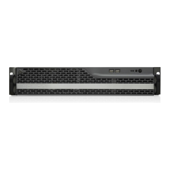
Page 17: Front-Panel
Front-Panel With Bezel on Handles HDD LED Power LED Opening clip Reset button Lock Power button USB 2.0 ports Chapter 2: Overview... -
Page 18: How To Open/Lock The Bezel
How to open/lock the bezel ? To open the bezel: 1. Turn a quarter turn counter-clockwise the lock 2. Push the opening clip to the right. Pull out the bezel. Chapter 2: Overview... - Page 19 Without the Bezel Rack mounting ears HDD LED Power LED Filter Reset button Hot Swap Hard Drives Power button USB 2.0 ports Chapter 2: Overview...
-
Page 20: Back Panel
Back Panel Power Supply Units I/O Back Panel Opening screw PCI slots openings VGA port Chapter 2: Overview... -
Page 21: I/O Panel
I/O Panel PS/2 mouse and keyboard port USB 2.0 ports USB BIOS Flashback button DM LAN port Optical S/PDIF Out port LAN ports USB 3.0 ports (Disabled by Audio I/O ports default) Chapter 2: Overview... -
Page 22: Motherboard Overview
2.2 Motherboard Overview Chapter 2: Overview... - Page 23 ATX power connectors (24-pin System panel connector (20-8 EATXPWR; 8-pin EATX12V, 6- pin PANEL) pin EATX12V_1) DDR3 DIMM slots USB 2.0 connector (10-1 pin USB78; USB910; A-Type USB11) LGA2011 CPU Socket Reset button CPU, REAR, Power, Front, AUX Power-on button FANSENSE connectors (4-pin CPU_FAN1/2;...
-
Page 24: Pci Extension Slots
PCI Extension Slots ˇ Ensure to unplug the power cord before adding or removing expansion cards. Failure to do so may cause you physical injury and damage motherboard components. not available not available PCIe 3.0 x16 slot (x16 Gen3 Link) (Auto switch to x8 link if slot 2 is occupied) not available PCIe 3.0 x16 slot (x16 Gen3 Link) (Auto switch to x8 link... - Page 25 IRQ assignments for this motherboard SMBus Controller shared USB 2.0 Controller 1 shared USB 2.0 Controller 2 shared High DefinitionAudio shared HECI shared SATA Controller 1 shared SATA Controller 2 shared Asmedia USB3.0 shared Controller 1 Asmedia USB3.0 shared Controller 2 LAN Controller 1 shared LAN Controller 2...
-
Page 26: Ram Dimm
RAM DIMM The motherboard comes with eight Double Data Rate 3 (DDR3) Dual Inline Memory Module (DIMM) slots. Recommended memory configuration Chapter 2: Overview... -
Page 27: Chapter 3: Configuration / Setup
Chapter 3 Configuration / Setup Chapter 3: Configuration / Setup... -
Page 28: Onboard Switches
3.1 Onboard switches Onboard switches allow you to fine-tune performance when working on a bare or open-case system. This is ideal for overclockers and gamers who continually change settings to enhance system performance. Power-on button The motherboard comes with a power-on switch that allows you to power up or wake up the system. The switch also lights up when the system is plugged to a power source indicating that you should shut down the system and unplug the power cable before removing or plugging in any motherboard component. - Page 29 Reset button Press the reset switch to reboot the system. Chapter 3: Configuration / Setup...
- Page 30 EPU switch Turning this switch to Enable will automatically detect the current PC loadings and intelligently moderate the power consumption. We recommend that you do not change these settings. Activating the EPU switch while running an overclocked BIOS profile could tend to performance drop.
- Page 31 TPU switch Turning this switch to Enable will automatically optimize the system for fast, yet stable clock speeds. We recommend that you do not change these settings. Activating the TPU switch while running an overclocked BIOS profile could tend to performance drop.
- Page 32 MemOK! switch Installing DIMMs that are incompatible with the motherboard may cause system boot failure, and the DIAG_DRAM near the MemOK! switch light continuously. Press and hold the MemOK! switch until the DIAG_DRAM starts blinking to begin automatic memory compatibility tuning for successful boot.. Chapter 3: Configuration / Setup...
-
Page 33: Knowing Bios
3.2 Knowing BIOS BIOS (Basic Input and Output System) stores system hardware settings such as storage device configuration, overclocking settings, advanced power management, and boot device configuration that are needed for system startup in the motherboard CMOS. The custom BIOS settings apply to most conditions to ensure optimum performance. We recommend that you do not change the custom BIOS settings Inappropriate settings of the BIOS may result to instability or failure to boot. -
Page 34: Bios Overview
BIOS Overview Menu items Submenu item Pop-up window Configuration field Scroll bar Menu bar Navigation keys General help Chapter 3: Configuration / Setup... - Page 35 Menu bar The menu bar on top of the screen has the following main items: Main For changing the basic system configuration Ai Tweaker not available Advanced For changing the advanced system settings Monitor For displaying the system temperature, power status, and changing the fan settings. Boot For changing the system boot configuration Tool...
-
Page 36: Main Menu
Main Menu The Main menu screen appears when you enter the Advanced Mode of the BIOS Setup program. The Main menu provides you an overview of the basic system information, and allows you to set the system date, time, language, and security settings. -
Page 37: Advanced Menu
3.4 Advanced Menu The Advanced menu items allow you to change the settings for the CPU and other system devices. Chapter 3: Configuration / Setup... -
Page 38: Cpu Configuration
CPU Configuration The items in this menu show the CPU-related information that the BIOS automatically detects. We recommend that you do not change these settings. Changing the CPU settings while running an overclocked BIOS profile could tend to performance drop. Scroll down to display the following items: Intel Adaptive Thermal Monitor [Enabled] This function includes TM1, TM2, and EMTTM. - Page 39 Hyper-threading [Enabled] The Intel Hyper-Threading Technology allows a hyper-threading processor to appear as two logical processors to the operating system, allowing the operating system to schedule two threads or processes simultaneously. [Disabled] Only one thread per activated core is enabled. Disabled for other OS (OS not optimized for Hyper- Threading Technology).
- Page 40 Enhanced Intel SpeedStep Technology [Disabled] Enhanced Intel SpeedStep Technology (EIST) allows the system operation to dynamically adjust processor voltage and cores frequency, which can result in decreased average power consumption and decreased average heat production. [Disabled] The CPU runs at its default speed. [Enabled] The operating system controls the CPU speed.
-
Page 41: System Agent Configuration
System Agent Configuration PCIEX16_1/2 Link speed [GEN3] Allows you to select the target link speed. Configuration options: [GEN1] [GEN2] [GEN3]. PCIEX16_3/4Link speed [GEN3] Allows you to select the target link speed. Configuration options: [GEN1] [GEN2] [GEN3]. PCIEX16_5 Link speed [GEN3] Allows you to select the target link speed. -
Page 42: Sata Configuration
Sata Configuration While entering Setup, the BIOS automatically detects the presence of SATA devices. The SATA Port items show Not Present if no SATA device is installed to the corresponding SATA port. SATA Mode [AHCI Mode] Allows you to set the SATA configuration. [Disabled] Disables the SATA function. - Page 43 SATA6G_1 (Gray) Hot Plug [Disabled] This item appears only when you set the previous item to [AHCI Mode] and [RAID mode]. It allows users to enable/disable SATA Hot Plug Support. Configuration options: [Disabled] [Enabled]. SATA6G_2 (Gray) Hot Plug [Disabled] This item appears only when you set the previous item to [AHCI Mode] and [RAID mode]. It allows users to enable/disable SATA Hot Plug Support.
-
Page 44: Usb Configuration
USB Configuration The items in this menu allow you to change the USB-related features. ˇ The USB Devices item shows the auto-detected values. If no USB device is detected, the item shows None. Legacy USB Support [Enabled] [Disabled] The USB devices can be used only for the BIOS setup program. [Enabled] Enables the support for USB devices on legacy operating systems (OS). -
Page 45: Onboard Device Configuration
Onboard Device Configuration Azalia HD Audio [Disabled] [Disabled] Disables the controller. [Enabled] Enables the High Definition Audio Controller. Front Panel Type [HD] Allows you to set the front panel audio connector (AAFP) mode to legacy AC97 or high-definition audio depending on the audio standard that the front panel audio module supports. - Page 46 Intel I210 LAN1 Enable [Enabled] [Disabled] Disables the controller. [Enabled] Enables the Intel LAN1 controller. Intel I210 LAN1 OpROM [Enabled] This item appears only when you set the previous item to [Enabled] and allows you to enable or disable the LAN1 PXE OptionRom of the Intel LAN controller.
-
Page 47: Apm
Restore AC Power Loss [Power Off] [Power On] The system goes into on state after an AC power loss. [Power Off] The system goes into off state after an AC power loss. [Last State] The system goes into either off or on state, whatever the system state was before the AC power loss. Power On By PCIE/PCI [Disabled] [Disabled] Disables the PCIE devices from generating a wake event. -
Page 48: Network Stack
Network Stack Network Stack [Disable] This item allows user to disable or enable the UEFI network stack. Configuration options: [Disabled] [Enabled]. ˇ The following item appears only when you set the Network Stack to [Enabled]. IPV4/IPV6 PXE Support [Enabled] Allows to enable or disable the IPV4/IPV6 PXE boot option. Configuration options: [Disabled] [Enabled]. - Page 49 The Monitor menu displays the system temperature/power status, and allows you to change the fan settings. Scroll down to display the following items: Scroll down to display the following items: CPU Temperature / MB / TR1 / TR2 Temperature [xxxºC/xxxºF] The onboard hardware monitor automatically detects and displays the CPU, motherboard, TR1, and TR2 temperatures.
- Page 50 CPU Q-Fan Control [Disabled] [Disabled] Disables the CPU Q-Fan control feature. [Enabled] Enables the CPU Q-Fan control feature. CPU Fan Speed Low Limit [600 RPM] This item appears only when you enable the CPU Q-Fan Control feature and allows you to disable or set the CPU fan warning speed in case the fan stops working.
- Page 51 REAR Fan 1 Fan Profile [Standard] This item appears only when you enable the REAR Fan 1 Q-Fan Control feature and allows you to set the appropriate performance level of the chassis fan. [Standard] The chassis fan will automatically adjust depending on the chassis temperature. [Silent] Minimizes the fan speed for quiet rear fan operation [Turbo]...
- Page 52 FRNT Fan 1 Fan Max. Duty Cycle (%) [100] Use the <+> and <-> keys to adjust the maximum FRNT fan duty cycle. The values range from 60% to 100%. The minimum value cannot be lower than the setting of the Min Duty Cycle. FRNT Fan 1 Lower Temperature [40] (in Celsius) Displays the lower limit of the FRNT 1 temperature.
-
Page 53: Boot Menu
3.6 Boot Menu The Boot menu items allow you to change the system boot options. Boot Configuration Fast Boot [Enabled] [Enabled] Select to accelerate the boot speed. [Disabled] Select to go back to normal boot. Chapter 3: Configuration / Setup... - Page 54 USB Support [Partial Initialization] [Disabled] All USB devices will not be available until OS boot up for the fastest POST time. [Full All USB devices will be available during POST. This process will extend the POST time. Initialization] [Partial For a faster POST time, only the USB ports with keyboard and mouse connections will be detected. Initialization] PS/2 Keyboard and Mouse Support [Auto] Select any of these settings when PS/2 keyboard and mouse are installed.
- Page 55 [Enabled] The system waits for the <F1> key to be pressed when error occurs. Option ROM Messages [Force BIOS] [Force BIOS] The third-party ROM messages will be forced to display during the boot sequence. [Keep Current] The third-party ROM messages will be displayed only if the third-party manufacturer had set the add-on device to do so.
- Page 56 Key Management This item appears only when you set OS Type to [Windows UEFI Mode]. It allows you to manage the Secure Boot keys. Clear Secure Boot keys This item appears only when you load the default Secure Boot keys. This item allows you to clear all default Secure Boot keys.
-
Page 57: Tools Menu
Configuration options: [Yes] [No] ˇ The db file must be formatted as a UEFI variable structure with time-based authenticated variable. DBX Management The dbx (Revoked Signature database) lists the forbidden images of db items that are no longer trusted and cannot be loaded. -
Page 58: Asus Ez Flash 2 Utility
ASUS EZ Flash 2 Utility Allows you to run ASUS EZ Flash 2 Utility to update BIOS. When you press <Enter>, a confirmation message appears. Use the left/right arrow key to select between [Yes] or [No], then press <Enter> to confirm your choice. ASUS DRAM SPD Information This menu shows information on the DIMM slots. -
Page 59: Server Mgmt Menu
Label Allows you to input the label of setup profile. Save to Profile Allows you to save the current BIOS settings to the BIOS Flash, and create a profile. Key in a profile number from one to eight, or use <+> and <-> keys to adjust the number. Press <Enter>, and then select Yes. Load from Profile Allows you to load the previous BIOS settings saved in the BIOS Flash. -
Page 60: System Event Log
O/S Wtd Timer Timeout [10 minutes] Allows you to configure the length of the O/S Boot Watchdog Timer. Not available if O/S Boot Watchdog Timer is disabled. Configuration options: [5 minutes] [10 minutes] [15 minutes] [20 minutes] O/S Wtd Timer Policy [Reset] Allows you to configure how the system should respond if the OS Boot Watchdog Timer expires. -
Page 61: Bmc Network Configuration
BMC network configuration Configuration Address source [Previous State] Select to configure LAN channel parameters statically or dynamically (by BIOS or BMC). Unspecified option will not modify any BMC network parameters during BIOS phase. Configuration options: [Previous State] [Static Mode] [DHCP Mode] ˇ... -
Page 62: Ipv6 Bmc Network Configuration
IPv6 BMC network configuration Configuration Address source [Previous State] Select to configure LAN channel parameters statically or dynamically(by BIOS or BMC). Configuration options: [Previous State] [Static Mode] [DHCP Mode] ˇ The following items appear only when you set Configuration Address source to [Static Mode]. Station IP address [0.0.0.0] Allows you to key in Station IP address. -
Page 63: Event Logs Menu
3.9 Event Logs menu The Event Logs allows you to change or view the event log settings. Change Smbios Event Log Settings Press <Enter> to change the Smbios Event Log configuration. Chapter 3: Configuration / Setup... - Page 64 Enabling/Disabling Options Smbios Event Log [Enabled] Change this to enable or disable all features of Smbios Event Logging during boot. Configuration options: [Disabled] [Enabled] Erasing Settings Erase Event Log [No] Choose the options for erasing Smbios Event Log. Erasing is done prior to any logging activation during reset. Configuration options: [No] [Yes, Next reset] [Yes, Every reset] When Log is Full [Do Nothing] Allows you to choose the options for reactions to a full Smbios Event Log.
-
Page 65: Exit Menu
3.10 Exit menu The Exit menu items allow you to load the optimal default values for the BIOS items, and save or discard your changes to the BIOS items. You can access the EZ Mode from the Exit menu. Load Optimized Defaults This option allows you to load the default values for each of the parameters on the Setup menus. -
Page 66: Updating Bios
3.11 Updating BIOS The CIARA technologies DMS website publishes the latest BIOS versions to provide enhancements on system stability, compatibility, or performance. However, BIOS updating is potentially risky. If there is no problem using the current version of BIOS, DO NOT manually update the BIOS. Inappropriate BIOS updating may result in the system’s failure to boot. Carefully follow the instructions of this chapter to update your BIOS if necessary. - Page 67 3. Once in the BIOS, the Main tab will be displayed. 4. Using the arrow key on your keyboard, navigate to the tab “Tool”. Select “ASUS EZ Flash 2 Utility” and hit “Enter”. Chapter 3: Configuration / Setup...
- Page 68 5. Select the BIOS that want to update and hit enter. 6. A popup will open asking if you want to read this file. Select Ok. Chapter 3: Configuration / Setup...
- Page 69 7. After few seconds, the message will change to “Do you really want to update BIOS?”. Select OK. 8. Once the BIOS updated, a confirmation message will pop up. Hit “Enter” to reboot the system. Chapter 3: Configuration / Setup...
- Page 70 9. At reboot, the system will stop during POST. Press F1 to go run BIOS. 10. The BIOS will load with the default settings. Press F7 to load the advanced Mode and load the profiles. Chapter 3: Configuration / Setup...
- Page 71 Load profiles from a USB key. Insert a FAT formatted USB key containing the Profiles in the unit you want to update. 1. While the system booting, hit “del”. The following screen will appear. Hit “ESC” to access the BIOS. 2.
- Page 72 3. Using the arrow key on your keyboard, navigate to the tab “Tool”. Select ASUS O.C Profile and hit “Enter”. 4. Select Load/Save CMOS Profile From/to USB drive and hit “Enter” Chapter 3: Configuration / Setup...
- Page 73 5. Select the first Profile that you want to load and hit enter. 6. No message will be displayed. Hit “ESC” to leave the OC Profile Utility. Then select “Ok” to confirm. Chapter 3: Configuration / Setup...
- Page 74 7. In the Save to Profile field, enter the number that you want the Label to be saved to and hit enter. 8. A confirmation pop up will appear. Select Yes. 9. Repeat steps 4 to 8 to add more profiles. Chapter 3: Configuration / Setup...
- Page 75 Load profiles. 1. While the system booting, hit “del”. The following screen will appear. Hit “ESC” to access the BIOS. 2. Once in the BIOS, the Main tab will be displayed. Chapter 3: Configuration / Setup...
- Page 76 3. Using the arrow key on your keyboard, navigate to the tab “Tool”. Select ASUS O.C Profile and hit “Enter”. 4. In the Load from Profile tab, select the number of the Profile to load and hit “Enter”. Chapter 3: Configuration / Setup...
- Page 77 5. A confirmation message will open. Select yes. 6. Hit F10 (Save and Exit). Select yes. System will reboot. Chapter 3: Configuration / Setup...
-
Page 78: Asus Ez Flash 2 Utility
ASUS EZ Flash 2 utility The ASUS EZ Flash 2 feature allows you to update the BIOS without having to use a bootable floppy disk or an OS-based utility. ˇ Before you start using this utility, download the latest BIOS from the ASUS website at www.asus.com. To update the BIOS using EZ Flash 2: 1. -
Page 79: Asus Crashfree Bios 3 Utility
ˇ This function can support devices such as a USB flash disk with FAT 32/16 format and single partition only. ˇ DO NOT shut down or reset the system while updating the BIOS to prevent system boot failure! ˇ Ensure to load the BIOS default settings to ensure system compatibility and stability. Select the Load Optimized Defaults item under the Exit menu. -
Page 80: Asus Bios Updater
ASUS BIOS Updater The ASUS BIOS Updater allows you to update the BIOS in DOS environment. This utility also allows you to copy the current BIOS file that you can use as a backup when the BIOS fails or gets corrupted during the updating process. ˇ... - Page 81 4. At the FreeDOS prompt, type d: and press <Enter> to switch the disk from Drive C (optical drive) to Drive D (USB flash drive). Updating the BIOS file To update the BIOS file using BIOS Updater: 1. At the FreeDOS prompt, type bupdater /pc /g and press <Enter>. 2.
- Page 82 3. Press <Tab> to switch between screen fields and use the <Up/Down/Home/End> keys to select the BIOS file and press <Enter>. BIOS Updater checks the selected BIOS file and prompts you to confirm BIOS update. 4. Select Yes and press <Enter>. When BIOS update is done, press <ESC> to exit BIOS Updater. Restart your computer.
-
Page 83: Chapter 4: Remote Management
Chapter 4 Remote Management Chapter 4: Remote Management... -
Page 84: Asmb7-Ikvm
The ORION HF210 comes installed on an Asus P9X79-WS-BMC Motherboard especially designed for CIARA Technologies in order to set the best over-clocking environment and provide extreme performances. For the first time in a single socket server, a true remote management is now available. - Page 85 Chipset Aspeed 2300 Internal RAM 224 MB for system 32 MB for video Internal ROM 32 MB Timers 32-bit Watchdog Timer Main Features IPMI 2.0 compliant and supports KVM over LAN Web-based user interface (remote management) Virtual media Network Bonding support Form Factor 22 mm x 17 mm 4.2 ASWM 2.0...
-
Page 86: Chapter 5 Maintenance
Chapter 5 Maintenance Chapter 5: Maintenance... -
Page 87: Upgrade
5.1 Upgrade Memory Upgrade to remove a DIMM Chapter 5: Maintenance... -
Page 88: Memory Test With Memok
Recommended memory configuration Memory Test with MemOK! Installing DIMMs that are incompatible with the motherboard may cause system boot failure, and the DIAG_DRAM near the MemOK! switch lights continuously. Press and hold the MemOK! switch until the DIAG_DRAM starts blinking to begin automatic memory compatibility tuning for successful boot. -
Page 89: Disk Replacement
5.2 Disk replacement The ORION HF210 comes with 4 hot swappable bay drives. This system allows you to mount/unmount disks faster without even shutting down the device. Chapter 5: Maintenance... - Page 90 To unmount the disk: 1. Push on the right side button 2. Pull the tab in order to slide out the disk tray. 3. Unscrew the disk from the tray. Chapter 5: Maintenance...
-
Page 91: Fan Replacement
5.3 Fan replacement 1. Shut down the machine. 2. Open the top of the machine. 3. Unplug the power cable. Chapter 5: Maintenance... - Page 92 4. Pull out the fan block. Chapter 5: Maintenance...
-
Page 93: Chapter 6: Troubleshooting
Chapter 6 Troubleshooting Chapter 6: Troubleshooting... -
Page 94: Onboard Leds
6.1 Onboard LEDs Diagnosis LED These diagnosis LEDs of CPU, DRAM, VGA card, and HDD indicate key component status during POST (Power-on Self Test), providing an elegant embellishment to the motherboard design. The LED lights will flash sequentially during system bootup. If an error is found, the LED next to the error device will continue lighting until the problem is solved. -
Page 95: Epu Led
EPU LED The EPU LED lights when the EPU switch is turned to Enable. Chapter 6: Troubleshooting... -
Page 96: Tpu Led
TPU LED The TPU LED lights up when the TPU switch is turned to Enable. Chapter 6: Troubleshooting... -
Page 97: Q-Code Led
Q-Code LED The Q-Code LED design provides you the 2-digit display, allowing you to know the system status. Refer to the Q-Code table on the next page for details. Chapter 6: Troubleshooting... -
Page 98: Q-Code Table
Q-Code Table Code Description Not used Power on. Reset type detection (soft/hard). AP initialization before microcode loading System Agent initialization before microcode loading PCH initialization before microcode loading Initialization before microcode loading Microcode loading AP initialization after microcode loading System Agent initialization after microcode loading PCH initialization after microcode loading Initialization after microcode loading Cache initialization... - Page 99 Code Description S3 Resume is stared (S3 Resume PPI is called by the DXE IPL) S3 Boot Script execution Video repost OS S3 wake vector call E4-E7 Reserved for future AMI progress codes S3 Resume Failed S3 Resume PPI not Found S3 Resume Boot Script Error S3 OS Wake Error EC-EF...
- Page 100 Code Description PCI Bus Request Resources PCI Bus Assign Resources Console Output devices connect Console input devices connect Super IO Initialization USB initialization is started USB Reset USB Detect USB Enable 9E-9F Reserved for future AMI codes IDE initialization is started IDE Reset IDE Detect IDE Enable...
- Page 101 Code Description No Space for Legacy Option ROM No Console Output Devices are found No Console Input Devices are found Invalid password Error loading Boot Option (Load Image returned error) Boot Option is failed (Start Image returned error) Flash update is failed Reset protocol is not available ACPI/ASL Checkpoints Code Description...
-
Page 102: Cpu Warning Led (Err_Cpu1)
CPU Warning LED (ERR_CPU1) The CPU warning LEDs light up to indicate impending failure of the CPU. Chapter 6: Troubleshooting... -
Page 103: Dimm Warning Led (Err_Dimma1/2;Err_Dimmb1/2;Err_Dimmc1/2;Err_Dimmd1/2)
DIMM warning LED (ERR_DIMMA1/2;ERR_DIMMB1/2;ERR_DIMMC1/2;ERR_ DIMMD1/2) The DIMM warning LEDs light up to indicate an impending failure of the corresponding DIMMs. Chapter 6: Troubleshooting... -
Page 104: Baseboard Management Controller Led (Bmc_Led1)
Baseboard Management Controller LED (BMC_LED1) The green heartbeat LED blinks per second to indicate that the ASMB7 is working normally. Chapter 6: Troubleshooting... -
Page 105: Dimm Warning Led
DIMM warning LED (ERR_DIMMA1/2 The CATTERR LED indicates that the system has experienced a fatal or catastrophic error and cannot continue to operate. Chapter 6: Troubleshooting... -
Page 106: Battery Removal And Installation
6.2 Battery Removal and Installation Battery Removal To remove the onboard battery, follow the steps below: 1. Power off your system and unplug your power cable. 2. Locate the onboard battery as shown below. 3. Using a tool such as a pen or a small screwdriver, push the battery lock outwards to unlock it. Once unlocked, the battery will pop out from the holder. -
Page 107: Contact Information
- Indicate the serial number of the machine(s) - Write a brief description of the issue - Indicate your address and the contact person name. or please call 1-855-597-4913 How to contact CIARA Technologies CIARA Technologies 9300, Transcanada Highway Saint-Laurent, Québec...
Need help?
Do you have a question about the Orion HF-210 and is the answer not in the manual?
Questions and answers