Table of Contents
Advertisement
Advertisement
Table of Contents

Related Manuals for Ciara ORION HF210-G5

Summary of Contents for Ciara ORION HF210-G5
- Page 1 ORION HF210-G5 User Manual...
-
Page 2: About This User Manual
1. About this User Manual This user manual contains the information on Installation and maintenance of the ORION HF210-G5. Caution: Experienced technicians should perform the Installation and maintenance. Document title: ORION HF210-G5 Document number: Revision 03 Document update date: January 2021 The following Notes, Cautions and Warnings might appear in this user manual. -
Page 3: Table Of Contents
2. Table of Contents Contents About this User Manual................................................1 Table of Contents ..................................................2 ORION HF210-G5 Specifications ..............................................5 Chassis Overview ..................................................6 Front Panel Components ................................................7 Back Panel Components ................................................8 Accessory Boxes & Rails ................................................9 Labelling ..................................................... - Page 4 28.3.1 Product Information ................................................ 63 28.3.2 Firmware Information ..............................................63 28.3.3 Network Information ............................................... 64 28.3.4 Sensor Monitoring ................................................64 28.3.5 Event Logs ..................................................64 28.4 Sensors ....................................................65 28.4.1 Sensor detail: ................................................... 65 28.5 System Information ................................................66 28.5.1 FRU Information ................................................66 28.5.2 Chassis Information .................................................
- Page 5 28.7.17. CPU Profile Selection ..............................................110 28.8 Remote Control ..................................................111 28.9 Image Redirection ................................................112 28.9.1 Remote Media ................................................112 28.10 Power Control ..................................................113 28.11 Miscellaneous ..................................................114 28.11.1 UID Control .................................................. 114 28.11.2 Post Snoop ................................................... 114 28.12 Maintenance ..................................................
-
Page 6: Orion Hf210-G5 Specifications
Estimated Weight 37.4 lb / 16.5 kg Warranty CIARA’s limited hardware warranty includes a one year, parts and labour with return to CIARA USA or Canada. Customers may purchase an extended warranty of up to 3 years on parts and labour with different support levels. Please contact CIARA at 1-877-242-7272 for complete warranty details including limitations and transferability. -
Page 7: Chassis Overview
4. Chassis Overview The following illustrations are the ORION HF210-G5 chassis Front, Back and Side views. -
Page 8: Front Panel Components
Front Panel Components ITEM DESCRIPTION 2x USB 3.1 Gen1 Power Button HDD LED Power LED Reset 2x Drive Bay... -
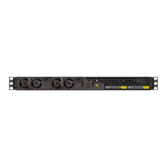
Page 9: Back Panel Components
6. Back Panel Components ITEM DESCRIPTION UID Switch (UID1) VGA Port (VGA1) Serial Port (COM1) LAN RJ-45 Port (IPMI_LAN) HDMI Port (HDMI) 10G LAN RJ-45 Port (LAN1) 10G LAN RJ-45 Port (LAN2) USB 3.1 Gen2 Ports (USB31_1_2) 1G LAN RJ-45 Port (LAN3) USB 3.1 Gen2 Ports (USB31_3_4) 1G LAN RJ-45 Port (LAN4) PCIe x16 (FH/FL/DW) -
Page 10: Accessory Boxes & Rails
Accessory Box #1 with GPU Cables and Brackets Accessory Box #2 with (2) Power Cables Also the ORION HF210-G5 server includes (1) bezel box: The rails, bezel box and both accessory boxes are placed as shown below in the box with the server. -
Page 11: Labelling
8. Labelling This section contains information on the different labels found on the server. 8.1 Power supplies cage... -
Page 12: Serial Number And Model Number Labels On Mylar
8.2 Serial Number and Model Number Labels on Mylar Serial Number Model Number Front Serial Number Model Number Back 8.3 HDD trays... -
Page 13: Support And Certification Labels
8.4 Support and Certification Labels... -
Page 14: Chassis Layout
9. Chassis Layout The following illusration shows inside of the ORION HF210-G5 system. -
Page 15: Motherboard Layout
10. Motherboard Layout The following picture shows the motherboard layout in the ORION HF210-G5 system. - Page 16 Feature Specification Form factor mATX Processor Support Support Intel® 10th Gen. Core™ i9/i7/i5/i3, Pentium, Celeron® Series Processors Chipset Intel® Z490 4 x 288-pin DDR4 DIMM slots Memory Support up to 128GB DDR4 non-ECC UDIMM 2 x RJ45 GLAN by Intel® i210 2 x RJ45 10G base-T by Intel®...
-
Page 17: Detailed Motherboard Layout
11. Detailed Motherboard Layout The following illustration shows the detailed motherboard layout in the ORION HF210-G5 system. -
Page 18: Connector Functionality
Front VGA Header (FRNT_VGA1) SATA3 Connector (SATA_5) 2 x 288-pin DDR4 DIMM Slots (DDR4_A1, DDR4_B1, Blue) SATA3 Connector (SATA_6) (Not supported for Z490D4U-2L2T) PSU SMBus (PSU_SMB1) SATA3 Connector (SATA_7) (Not supported for Z490D4U-2L2T) ATX Power Connector (ATXPWR1) SATA3 DOM Connector (SATA_0), Red 2 x 288-pin DDR4 DIMM Slots (DDR4_A2, DDR4_B2, White) SATA DOM Power Connector (SATA_PWR1) Chassis Fan Connector (FAN1) -
Page 19: Jumper Functionality
11.2 Jumper Functionality... -
Page 21: Led Functionality
11.3 LED Functionality Item Status Description SB_PWR1 Green STB PWR ready FAN1_LED1 Amber FAN1 failed FAN2_LED1 Amber FAN2 failed FAN3_LED2 Amber FAN3 failed FAN4_LED4 Amber FAN4 failed FAN5_LED2 Amber FAN5 failed FAN6_LED1 Amber FAN6 failed FAN7_LED3 Amber FAN7 failed BMC_LED1 Green BMC heartbeat LED... -
Page 22: Block Diagram
11.4 Block Diagram... -
Page 23: Removing The Chassis Cover
12. Removing the Chassis Cover This section contains information on how to remove the chassis cover from the system. Step 1: Turn the Knob anti-clockwise by using Philips screwdriver type 2. Step 2: Slide the Rear Top Cover towards the back of the system to release the cover. -
Page 24: Installing The Chassis Cover
13. Installing the Chassis Cover This section contains information on how to install the Chassis cover in the system. Step 1: Slide the cover towards the front of the system to close the cover. Step 2: Turn the Knob clockwise by using Philips screwdriver type 2. -
Page 25: How To Clear The Cmos With Battery And Pad
14. How to clear the CMOS with battery and pad This section contains information on how to clear the CMOS by and battery and CMOS Pad. 14.1 Clear CMOS by Battery Step 1: Power system off. Step 2: Unplugged power cable from system. Step 3: Take off the chassis top cover and then locate the CMOS battery on the motherboard. - Page 26 Step 5: Press the lock on the left side and place the CMOS battery again gently. Step 6: Cover up the Chassis top cover and then Plug the power cable back in. Step 7: Turn system ON Step 8: Allow system to go through a complete power cycle in order to initialize all components.
-
Page 27: Clear Cmos By Cmos Pad
14.2 Clear CMOS by CMOS Pad Step 1: Power system off. Step 2: Take off the chassis cover. Step 3: Remove the both PCI-e riser extender from the PCI-e connector on the motherboard. Step 4: Locate the clear CMOS Pad. (Squared in red). Step 5: Use a flathead screwdriver or other piece of metal to short the two halves together for 30 seconds. -
Page 28: How To Replace The Cmos Battery
15. How to replace the CMOS battery: This section contains information on how to replace the CMOS battery in the system. Step 1: Power system off. Step 2: Unplugged power cable from system. Step 3: Take off the chassis top cover and then locate the CMOS battery on the motherboard. Step 4: Press the lock on the left side in order to CMOS battery to come up. - Page 29 Step 5: Press the lock on the left side and replace the new CMOS battery gently. Step 6: Cover up the Chassis top cover and then Plug the power cable back in. Step 7: Turn system ON Step 8: Allow system to go through a complete power cycle in order to initialize all components.
-
Page 30: Replacing Pcie Card
16. Replacing PCIe Card This section contains information on how to replace the PCIe card 1 and 2. 16.1 Replacing PCIE Card 1 Step 1: Pull the tab of the PCIe release latch and rotate to the top. Step 2: Pull the PCIe card out of the slot. - Page 31 Step 3: Twist the card and remove from chassis.
- Page 32 Step 4: Put another PCIe card in and install into the slot. Step 5: Rotate and close the PCIe release latch.
-
Page 33: Replacing Pcie 2 Card
16.2 Replacing PCIe 2 Card This section contains information on how to replace the PCIe 2 card. Step 1: Pull the tab of the PCIe release latch and rotate to the top. Step 2: Pull the PCIe card out of the slot and remove it. - Page 34 Step 3: Put another PCIe card in and install into the slot. Step 4: Rotate and close the PCIe release latch.
-
Page 35: Removing And Installing Memory Modules
17. Removing and Installing Memory Modules This section contains information on how to remove and install the Memory Modules. This motherboard provides four 288-pin DDR4 (Double Data Rate 4) DIMM slots, and supports Dual Channel Memory Technology. DIMM Size Per DIMM: Non-ECC UDIMM : 32GB, 16GB, 8GB, 4GB Caution: Handle each memory module only by the meomry cards edges, ensuring not touching the middle of memory module or mettalic contacts. -
Page 36: Installing Memory Module
17.2 Installing Memory Module Step 1: Identify the memory module socket. Step 2: Make sure that the Memory Module Ejectors on both ends are released. Step 3: Vertically press the memory module with your thumbs until the memory sits firmly in the memory socket. ❶... - Page 37 ❸...
-
Page 38: Replacing Swappable Ssd
18. Replacing Swappable SSD This section contains information on how to replace the swappable SSD in the front of the system. Step 1: Flip the button to the right and the latch pops out. Step 2: Pull out the SSD cage. - Page 39 Step 3: Turn over the cage and unscrew 4 screws. Step 4: Replace the SSD.
-
Page 40: Replacing Gpu
19. Replacing GPU This section contains information on how to replace the GPU in the Orion HF210-G5 system, in the PCIE 1 expansion slot. Caution: For all the GPUs used in the Orion HF210-G5 system, please install the GPU bracket assembly before installing the card. - Page 41 Step 3: Press down the PCIe slot lever and then pull the GPU out of slot. Step 4: Twist the GPU and remove the GPU.
- Page 42 Step 5: Remove the GPU bracket assembly and install to the new GPU. Step 6: Align the metal plate on the GPU with the rear panel then drop down the GPU.
- Page 43 Step 7: Slide the new GPU into the PCIe slot on the riser card. Step 8: Fasten the screws to mount the GPU bracket assembly with the chassis base.
- Page 44 Step 9: Rotate and close the PCIe release latch.
-
Page 45: Rack Mounting
20. Rack Mounting This section contains information on how to mount a system into the rack with the rack rails. Step 1. Install the rails into the rack. - Page 46 Step 2. Pull the inner and middle rails fully extended in lock position. Pull the white release button to slide out the inner rail. Step 3. Align the inner rail with the chassis mounting key, push and slide to lock.
- Page 47 Step 4. Horizontally slide the chassis into the middle rail until click. Step 5. Pull/Push the blue release button on the inner rail to unlock the chassis and then push the chassis into rack.
-
Page 48: Plugging The Power Cords
21. Plugging the Power Cords The following illustration shows how to connect the power cords to the back of the system. -
Page 49: Turning On The System
22. Turning on the System The following illustration indicates where the power button is located on the front of the server. -
Page 50: Dr. Debug Codes
23. Dr. Debug codes Dr. Debug is used to provide code information, which makes troubleshooting even easier. Please see the diagrams below for reading the Dr. Debug codes. Code Description Code Description 0x10 PEI_CORE_STARTED 0xA9 DXE_SETUP_START 0x11 PEI_CAR_CPU_INIT 0xAB DXE_SETUP_INPUT_WAIT 0x15 PEI_CAR_NB_INIT 0xAD... -
Page 51: Accessing Bios
24. Accessing BIOS: This section contains information on how to access to the system’s BIOS. Turn on the system and press the DEL or F2 button on the keyboard immediately after you see the following windows during the POST (Power-On-Self-Test) to enter in to the Bios. <Ctrl>... -
Page 52: Bios Menu
24. 1 BIOS Menu The BIOS Menu has the following sections: Main: To set up the system time/date information OC Tweaker: To load the user profiles. Advanced: To set up the advanced BIOS features Security: To set up the security features such as Supervisor Password and Enabling/Disabling Secure Boot. Boot: To set up the default system device to locate and load the Operating System. -
Page 53: Configuring Bmc Ip-Address Settings For Remote Management
25. Configuring BMC IP-Address Settings for remote management This section provides information on how to configure BMC IP-address settings for remote management from BIOS utility and BMC Web-GUI. 25.1 Configuring the BMC IP-Address Settings for Remote management in BIOS Utility This section contains information on how to configure BMC IP-address settings for remote management. - Page 54 Step 2: Under the Configure IPV4 support, select the Manual setting IPMI LAN and Choose Yes to choose the IP-address manually. Step 3: Under the Configuration address source, select either the Static or DHCP to choose the static IP-address source. If you select DHCP then IP-address assignment is done automatically and you can skip the later steps and press F10 to save changes and Exit to reboot the machine.
- Page 55 Step 4: If the Static IP selected then enter the values for the Station IP address, Current Subnet mask and Current Router IP address. Press F10 to Save and Exit to reboot the machine.
-
Page 56: Configuring The Static Bmc Ip-Address Settings For Remote Management In Bmc Web-Gui
25.2 Configuring the Static BMC IP-Address Settings for Remote management in BMC Web-GUI This section contains information on how to set a Static BMC IP-address settings for remote management in the BMC Web GUI. Step 1: In order to configure the Static IP-address through BMC Web-GUI, Turn ON the system and note down the BMC IP as seen below. Step 2: Launch the web browser, Type the current IP-address of the BMC, and enter the username as admin and password as admin. - Page 57 Step 3: When main menu of BMC appears then click on the Settings Step 4: Select the Network Settings...
- Page 58 Step 5: Select the Network IP Settings Step 6: Uncheck the Enable IPv4 DHCP, then enter the IPv4 Address, IPv4 Subnet and IPv4 Gateway and then click on Save...
- Page 59 Step 7: Click on OK and close the browser tab or browser. Launch the browser or new tab with the new BMC IP Address to verify if the changes has been successful.
-
Page 60: Using The Bmc (Ipmi) Web User Interface
26. Using the BMC (IPMI) Web User Interface The BMC (IPMI) Web user interface (GUI) provides an interface to access BMC (IPMI) Management Console which is used to configure, monitor and administer the ORION HF210-G5 systems. This Web-based GUI is supported on the following web browsers. -
Page 61: Accessing The Bmc (Ipmi) Management Console
27. Accessing the BMC (IPMI) Management Console In order to access the Management Console, Turn ON the system and note down the BMC (IMPI) IP address as seen below. Open the browser, type in the BMC (IPMI) IP address, you must have a valid Username and a Password. Both fields are required. Login Page The default username and password are both “admin”. -
Page 62: Viewing And Configuring The Bmc (Ipmi) Management Console
28. Viewing and Configuring the BMC (IPMI) Management Console After you successfully log into your Management Console, the Remote Management Console GUI appears. -
Page 63: Menu Bar
28.1 Menu bar The menu bar displays the following items. • Power Status • Dashboard • Sensor • System Information • Logs & Reports • Settings • Remote Control • Image Redirection • Power Control • Miscellaneous • Maintenance • Sign out 28.2 Quick Button and Logged-in User The user information and quick buttons are located at the top right of the Web GUI. -
Page 64: Dashboard
28.3 Dashboard The Dashboard displays the overall information about the status of the device. 28.3.1 Product Information The Product Information displays the following information. MB Model Name: Displays the motherboard model name. System Product: Displays the system product name. 28.3.2 Firmware Information The Firmware Information displays the following information. -
Page 65: Network Information
28.3.3 Network Information The Network Information of the device with the following fields is shown here. Click Details to view more information. MAC Address: Read-only field shows the MAC address of the device. V4 Network Mode: The v4 network mode of the device can be either static or DHCP. IPv4 Address: The IPv4 address of the device can be static or DHCP. -
Page 66: Sensors
28.4 Sensors The Sensor Readings page displays all the sensor related information. To open the Sensor Readings page, click Sensor from the menu. Click on any sensor to show more information about that particular sensor, including thresholds and a graphical representation of all associated events. -
Page 67: System Information
28.5 System Information This group of pages allows you to view system information. FRU Page FRU Information This page displays the FRU information. Select a FRU Device ID from the FRU Information section to view the details of the selected device. Sensor detail Page Available FRU Devices FRU device ID: Select the device ID from the drop-down list. - Page 68 • FRU File ID • Product Extra...
-
Page 69: Logs & Reports
28.6 Logs & Reports This group of pages allows you to view the logs. There are two pages under the Logs & Report. 28.6.1 IPMI Event Log This page displays the list of event logs occurred by the different sensors on this device. Double click on a record to see the details of that entry. You can use the sensor type or sensor name filter options to view those specific events or you can also sort the list of entries by clicking on any of the column headers. -
Page 70: Video Log
Filter By Type: The category can be All Events, System Event Records, OEM Event Records, BIOS Generated Events, SMI Handler Events, System Management Software Events, System Software - OEM Events, Remote Console software Events, or TerminalMode Remote Console software Events. Filter By Sensor: Filtering can be done with the sensors mentioned in the list. -
Page 71: Settings
28.7 Settings This group of pages allows you to access various configuration settings. Settings Page... -
Page 72: Data & Time
28.7.1 Data & Time This page allows administrator to set the date and time on the BMC. It can be used to configure either Date & Time or NTP (Network Time Protocol) server settings for the device. Date & Time Page Date &... -
Page 73: External User Services
28.7.2 External User Services This page is used to configure the external service. External User Services Page 28.7.2.1 LDAP/E-directory Settings LDAP is an Internet protocol that BMC can use to authenticate users. If you have an LDAP server configured on your network, you can use it as an easy way to add, manage and authenticate web users. - Page 74 General Settings: This page is used to configure LDAP/E-Directory settings. General Settings Page Enable LDAP/E-Directory Authentication: Check the box to enable LDAP/E-Directory authentication. Encryption Type: Select the encryption type for LDAP/E-Directory. Common Name Type: Select the Common Name Type for LDAP/E-Directory. Server Address: The IP address (IPv4 or IPv6) of LDAP/E-Directory server.
-
Page 75: Active Directory Settings
Role Groups: This page is used to add a new role group to the device. Alternatively, double click on a free slot to add a role group. Role Groups Page Group Name: Enter the name that identifies the role group. Group Domain: Enter the Role Group Domain where the role group is located. -
Page 76: Radius Settings
Role Groups: This page is used to add a new role group to the device. Alternatively, double click on a free slot to add a role group. Role Groups Page Group Name: Enter the name that identifies the role group. Group Domain: Enter the Role Group Domain where the role group is located. - Page 77 General RADIUS Settings: This page is used to configure Radius general settings. General RADIUS Settings Page Enable RADIUS Authentication: Check the box to enable Radius authentication. Server Address: The IP address of Radius server. Port: The port number of Radius server. Secret: The authentication secret of Radius server.
- Page 78 Advanced RADIUS Settings : This page is used to configure Advanced Radius authorization setting. Advanced RADIUS Settings Page Administrator: Configure Administrator with Vendor Specific Attribute in Server side. Operator: Configure Operator with Vendor Specific Attribute in Server side. User: Configure User with Vendor Specific Attribute in Server side. OEM Proprietary: Configure OEM Proprietary with Vendor Specific Attribute in Server side.
-
Page 79: Kvm Mouse Settings
28.7.3 KVM Mouse Settings The Redirection Console handles mouse emulation from local window to remote screen in either of three methods. KVM Mouse Setting Page Relative Positioning (Linux): Relative mode sends the calculated relative mouse position displacement to the server. Absolute Positioning (Windows): The absolute position of the local mouse is sent to the server. -
Page 80: Log Settings
28.7.4. Log Settings This page is used to configure the log settings. Log Settings Page 28.7.4.1. Log Settings Policy This page is used to configure the log policy for the event log. Linear Storage Policy: Check the option to enable linear storage policy for the event log. Circular Storage Policy: Check the option to enable circular storage policy for the event log... -
Page 81: Media Redirection Settings
28.7.5. Media Redirection Settings This page is used to configure the media into BMC for redirection. Media Redirection Settings Page... -
Page 82: General Settings
28.7.5.1 General Settings This page is used to configure general media settings. General Settings Page Remote Media Support: Check the box to enable Remote Media support. Mount CD/DVD: Check the box to enable Mount CD/DVD support. Server Address for CD/DVD Images: Displays the address of the server where the remote media images are stored. Path in server: Displays the Source path to the remote media images. -
Page 83: Remote Session
VMedia Instance Settings Page Floppy device instances: The number of floppy devices supported for Virtual Media redirection. CD/DVD device instances: The number of CD/DVD devices supported for Virtual Media redirection. Hard disk instances: The number of hard disk devices supported for Virtual Media redirection. Encrypt Media Redirection Packets: Check the box to enable Media Encryption support. -
Page 84: Network Settings
28.7.6. Network Settings This page is used to configure the network settings for the available LAN channels. Network Settings Page 28.7.6.1 Network IP Settings This page is used to configure the network IP settings. Network IP Settings Enable LAN: Check the box to enable the selected channel. LAN Interface: Lists the available LAN interfaces. - Page 85 IPv4 Default Gateway: Specify the static IPv4 default gateway for the selected channel. Enable IPv6: Check the box to enable the IPv6 for the selected channel. Enable IPv6 DHCP: Check the box to enable IPv6 DHCP support for the selected channel. IPv6 Index: Specify a static IPv6 Index to be configured for the selected channel.
-
Page 86: Network Bond Configuration
28.7.6.2. Network Bond Configuration This page is used to configure the network bond configurations. Network Bond Page Enable Bonding: Check this option to enable network bonding for network interface. Bond Mode: This field displays the Network bonding mode. Note: this field is not configurable. 28.7.6.3. - Page 87 DNS Enabled: Check the box to enable the DNS support. mDNS Enable: Check the box to enable the mDNS support. Host Name Settings: Choose either Automatic or Manual settings. Host Name: It displays host name of the device. If the Host setting is chosen as Manual, then specify the host name of the device. BMC Interface: To register the BMC through the Interfaces.
-
Page 88: Pam Order Settings
28.7.7 PAM Order Settings This page is used to configure the PAM ordering for user authentication. PAM Order Settings Page PAM Authentication Order: It shows the list of available PAM modules supported in BMC. Click and Drag the required PAM module to change its order. Note: 1. -
Page 89: Platform Event Filter
28.7.8. Platform Event Filter Platform Event Filter (PEF) provides a mechanism for configuring the BMC to take selected actions on event messages that it receives or has internally generated. These actions include operations such as system power-off, system reset, as well as triggering the generation of an alert. Platform Event Filter Page 28.7.8.1. - Page 90 Event Filters Configuration Page Enable this filter: Check the box to enable the PEF settings. Event Severity to trigger: Select any one of the Event severity from the list. Power Action: Select any one of the power action either Power down, Power reset or Power cycle from the drop-down list Alert Policy Group Number: Select any one of the alert policy group number from the drop-down list.
-
Page 91: Alert Policies
28.7.8.2 Alert Policies This page is used to configure the Alert Policy for the PEF configuration. You can add, delete or modify an entry in this page. Alert Policies Page... -
Page 92: Lan Destinations
Alert Policies: Click the Alert Policies section to configure the alert policies in the available slots. Alert Policies Page Policy Group Number: Displays the Policy number of the configuration. Enable this alert: Check the box to enable the policy settings. Policy Action: Choose any one of the Policy set values from the list. - Page 93 LAN Destination Configuration: Select any empty slot to configure LAN Destinations. LAN Destination Configuration Page LAN Channel: Displays LAN Channel Number for the selected slot (read only). LAN Destination: Displays ID for setting Destination Selector of Alert Policy (read only). SNMP Destination Address: Destination type can be either an SNMP Trap or an E-mail alert.
-
Page 94: Services
28.7.9. Services This page is used to displays the basic information about services running in the BMC. Services Page Services: Displays service name of the selected slot (read only). Status: Displays the current status of the service, either active or inactive state. Interfaces: It shows the interface in which service is running. - Page 95 View the active sessions: Click View icon to view the details about the active sessions for the service. Service Session Page Session ID: Displays the ID of the active sessions. Session Type: Displays the type of the active sessions. User ID: Displays the ID of the user. User Name: Displays the name of the user.
-
Page 96: Smtp Settings
28.7.10. SMTP Settings This is used to configure the SMTP settings of the device. SMTP Settings Page LAN Interface: Displays the list of LAN channels available. Sender Email ID: Enter the valid Sender Email ID on the SMTP Server. Primary SMTP Support: Check the box to enable SMTP support for the BMC. Primary Server Name: Enter the Machine Name of the SMTP Server. -
Page 97: Ssl Settings
28.7.11. SSL Settings This page is used to configure SSL certificate for the BMC. SSL Settings Page 28.7.11.1. View SSL Certificate This page is used to view the uploaded SSL certificate in readable format. View SSL certificate Page Note: This page provides a simple method to generate SSL certificate and it is not issued by a trusted Certificate Authority, you can upload a trusted certificate by yourself, if necessary. -
Page 98: Generate Ssl Certificate
28.7.11.2. Generate SSL Certificate This page is used to generate the SSL certificate based on configuration details. Generate SSL certificate Page Common Name(CN): Common name for which certificate is to be generated. Organization(O): Organization name for which the certificate is to be generated. Organization Unit(OU): Over all organization section unit name for which certificate is to be generated. -
Page 99: System Firewall
28.7.12. System Firewall This page is used to configure the firewall settings. The firewall rule can be set for an IP or range of IP Addresses or Port numbers. System Firewall Page 28.7.12.1. Firewall Settings General This page is used to configure general firewall settings. General Firewall Settings Page Existing Firewall Settings: This page is used to displays existing firewall settings. -
Page 100: General Firewall Settings
28.7.12.2. General Firewall Settings This page is used to add a new IP Address or Range to firewall settings. IP Firewall Rules Page Existing IP Rules: This page is used to displays existing IP rules. Existing IP Rules Page Add IP Rule: This page is used to displays add IP rule settings. - Page 101 28.7.12.3. Port Firewall Rules This page is used to add a new Port or Range to firewall settings. Port Firewall Rules Page Existing Port Rules: This page is used to displays existing port rules. Existing Port Rules Page Add Port Rule: This page is used to displays add port rule settings.
-
Page 102: User Management
28.7.13 User Management This page displays the current list of user slots for the server. You can add a new user and modify or delete the existing users. User Management Page Add a new user: To add a new user, select a free section and click on the empty section. Add User Page Username: Enter the name of the user. - Page 103 Serial Privilege: Select the serial privileges assigned to the user. KVM Access: Assign the KVM privilege for the user. VMedia Access: Assign the VMedia privilege for the user. Note: Both KVM and VMedia privilege will enable(disable) automatic when Network Privilege is administrator(other).
-
Page 104: Video Recording
28.7.14. Video Recording This page is used to configure video recording settings. Video Recording Page... -
Page 105: Port Firewall Rules
28.7.14.1. Port Firewall Rules This page is used to configure auto video recording settings. Auto Video Settings Page Video Trigger Settings: This page is used to configure the events that will trigger auto video recording function of the KVM server. Video Trigger Settings Page Critical Events (Temperature/Voltage): Trigger the recording by the critical events for Temperature/Voltage sensor. - Page 106 Record Video to Remote Server: Check the box to enable remote video support. If remote video support is enabled, then the video files will be stored in remote path. Maximum Dumps: Enter maximum dumps of the video. Maximum Duration(Sec): Enter maximum duration of the video. Maximum Size(MB): Enter maximum size of the video.
-
Page 107: Keep Share Nic Link Up
28.7.15. Keep Share NIC Link Up This page is used to configure share NIC (NCSI) PHY link up setting. Keep Share NIC Link Up Page Enable: Check the box to enable Keep Share NIC Link Up, share NIC PHY will keep link up, and it could avoid share NIC disconnection while system reset. -
Page 108: Fan Settings
28.7.16. FAN Settings This page is used to configure the Fan Settings. Fan Settings Page 28.7.16.1 Open Loop Control Table This page is used to configure the Open Loop Control Table. Open Loop Control Table Temp: Select to set the values from 0 to 120 degree Celsius. Duty: Select to set the values from 20 to 100. -
Page 109: Temperature Sensor And Corresponding Fan Table
The Temperature of Slow Down Fan Duty Cycle: To select the condition for temperature of slow down fan duty cycle. The Duty Cycle Percentage of Slow Down Fan Duty Cycle: To select the condition for duty cycle percentage of slow down fan duty cycle. The Time (Seconds) of Slow Down Fan Duty Cycle: To select the condition for time of slow down fan duty cycle. -
Page 110: Fan Mode
28.7.16.4 FAN Mode This page is to set the FAN Mode settings. Fan Mode Page Set Fan Duty For Manual Mode: To set the Fan Duty values for Manual Fans. Set Fan Control Mode: To set Fan Control Mode to be Default, either Manual or Customized. -
Page 111: Cpu Profile Selection
28.7.17. CPU Profile Selection This page is to set the CPU Profiles settings. You can select the overclock profiles and you must reboot the machine for the settings to take effect. CPU Profile Selection... -
Page 112: Remote Control
28.8 Remote Control This page is used to launch the remote console redirection. Remote Control Page Launch KVM: Click the button to open remote control KVM page. Launch Java KVM: Click the button to open Java KVM application. -
Page 113: Image Redirection
28.9 Image Redirection This page is used to configure the images into BMC for redirection Image Redirection Page 28.9.1. Remote Media This page is used to configure the remote images into BMC for redirection. Remote Media Page Media Type: Displays type of Media such as CD/DVD, Floppy and Hard disk. Media Instance: Displays total media instance count. -
Page 114: Power Control
28.10 Power Control This page is used to view and control the power of the server. Power Control Page Power Off: Select this option to immediately power off the server. Power On: Select this option to power on the server. Power Cycle: Select this option to first power off, and then reboot the system (cold boot). -
Page 115: Miscellaneous
28.11 Miscellaneous This page is used to configure miscellaneous settings. Miscellaneous Page 28.11.1 UID Control This page is used to control the UID of the chassis. UID Control Page Turn On: Select this option to turn on UID. Temporary On: Select this option to temporary turn on UID. (15 sec blink) Turn Off: Select this option to turn off UID. -
Page 116: Maintenance
28.12 Maintenance This page is used to do maintenance tasks on the device. Maintenance Page 28.12.1 Backup Configuration This page is used to back up the configuration. Backup Configuration Page Download Config: To download and save the configuration files backup from BMC to client system. 28.12.2 Restore Configuration This page is used to restore the configuration files from the client system to the BMC. -
Page 117: Firmware Update
TFTP Server Address: This field will be present if enable TFTP Server, the field is used to configure the address of TFTP server. TFTP Image Name: This field will be present if enable TFTP Server, the field is used to configure full source path with filename of TFTP server. TFTP Retry Count: This field will be present if enable TFTP Server, the field is used to configure the number of times to be retried in case a transfer failure occurs. -
Page 118: Restore Factory Defaults
28.12.6 Restore Factory Defaults This page is used to restore the factory defaults of the device firmware. Restore Factory Defaults Page Restore Factory Defaults: Click the button to restore configuration to factory default settings, the following settings will be restored. •... -
Page 119: Sign Out
28.13 Sign Out Click Sign Out to perform log out from the Web GUI. A Warning message will be prompted you to proceed further, click OK to log out else Cancel to retain the Web GUI. Sign Out Button and Prompt... -
Page 120: Updating Bios And Me
29. Updating Bios and ME This section contains information on how to update the BIOS and ME through the BMC port. Step 1: Insert the network cable in the dedicated BMC/IPMI Lan port. Step 2: Turn ON the machine. Step 3: Note down the BMC IP address detected as shown in the screenshot Step 4: Turn off the machine. - Page 121 Step 7: Click on ADVANCED Step 8: Click on Proceed to (… ) unsafe Step 9: Enter a Username: admin and Password: admin...
- Page 122 Step 10: Click on Maintenance and then click on BIOS Update Step 11: Select the Preserve BIOS configuration and then click on Choose File...
- Page 123 Step 12: Navigate the folder containing a BIOS then Select the BIOS and click on Open Step 13: Click on Start BIOS update...
- Page 124 Step 14: Click on OK Step 15: Wait until the Processing Window completes.
- Page 125 Step 16: Click on Proceed Step 17: Click on OK to proceed the BIOS update.
- Page 126 Step 18: Wait until the BIOS update completes and then click on OK...
-
Page 127: Profile Loading In Bios
30. Profile Loading in BIOS This section contains step-by-step instructions on how to upload the overclocking profile in the BIOS. Step 1: Turn ON the machine. Step 2: Press DEL or F2 continuously while the system is booting in order to get in to the BIOS. Once in the BIOS navigate in to the OC Tweaker menu and verify the User profiles to be the uploaded. - Page 128 Step 4- Enter Ok to restore the profile. Step 5- Press F10 and enter Yes to save the settings and then reboot the system.
-
Page 129: Downloading And Uploading A Profile In Linux
31. Downloading and Uploading a Profile in Linux This sections contains step-by-step instructions to download and upload the overclocking Profiles with Linux OS in the Orion HF210-G5 systems. The overclocking profiles can be downloaded or uploaded through remote or local system with Linux OS with the OCProfile utility. - Page 130 Example: In this example, there are eight multiple profiles being downloaded from the source overclocking profiles system either through a remote or local system with linux OS having OCProfile utility. ls-l Step 6: Type to verify that the downloaded overclocking profiles under the OCProfile directory.
-
Page 131: Uploading A Overclocking Profile
31.2 Uploading a Overclocking Profile Step 1: Login in to the Remote or local Linux system with the OCProfile utility. Step 2: Go in to the OCProfile directory. Step 3: Go under the linux directory and verify the existence of OCProfile utility. chmod 777 * Step 4: Enter the command to modify the file permissions for the OCProfile utility. - Page 132 Example: In this example, there are eight multiple profiles being uploaded to target system either through a remote system or local system with linux OS having OCProfile utility. Step 6: To load and activate a profile in BIOS refer to the instructions in shown in the section 32- Loading a Profile in BIOS...
-
Page 133: Drivers & Tools
32. Drivers & Tools This sections contains information about the drivers downloading and running common monitoring tools under Linux & windows on the Orion HF210-G5 systems. 32.1 Drivers Downloading The drivers are available on the Ciara’s website: https://ciaratech.com/support-center/ and you can search them either through a Filter or Search. -
Page 134: Monitoring Cpu Frequency In Linux
32.2 Monitoring CPU Frequency in Linux This sections contains the information on how to monitor CPU frequencies in the linux through i7z and turbostat utility. 32.2.1 i7z The i7z is a small open source utility that reports CPU frequency information. The information displayed covers Turbo Boost, frequencies, multipliers, temperature, and times spent in the C0/C1/C3/C6/C7 states. -
Page 135: Turbostat
32.2.2 Turbostat The turbostat is the base install utility in the linux and in case it is not possible to install or use i7z then run you can run turbostat and verify Bzy_Mhz for an actual frequency. 32.3 Verifying CPU Frequency for Windows This sections contains the information how to download and monitor CPU frequencies in the Windows through HWiNFO64 utility.
Need help?
Do you have a question about the ORION HF210-G5 and is the answer not in the manual?
Questions and answers