Riello TAU 2100 N Installation, Technical Assistance Service And System Management Manual
Hide thumbs
Also See for TAU 2100 N:

Related Manuals for Riello TAU 2100 N


Summary of Contents for Riello TAU 2100 N
- Page 1 TAU 2100-2600 N EN INSTALLATION, TECHNICAL ASSISTANCE SERVICE AND SYSTEM MANAGEMENT MANUAL...
- Page 2 MODEL CODE give dependable and safe service and to provide comfort in TAU 2100 N 20162158 the home for many years to come. Arrange for your boiler to be TAU 2600 N...
-
Page 3: Table Of Contents
Contents CONTENTS 1 GENERAL INFORMATION . . . . . . . . . . . . . . . . . . . . . . . . . . . . 4 General Safety Information . -
Page 4: General Information
GENERAL INFORMATION GENERAL INFORMATION GENERAL INFORMATION Precautions The operation of any appliance that uses fuel, electrical power General Safety Information and water demands that a number of fundamental safety pre- cautions be respected: The boiler is delivered in separate crates. Check that it is complete, undamaged and as ordered as soon as you re- It is forbidden to use electrical devices or equipment, such ceive it. -
Page 5: Description Of The Appliance
Titanium stabilized stainless steel, capa- ble of providing the best possible resistance to corrosion caused by acid condensate. RIELLO S.p.A. Via Ing.Pilade Riello 7 37045 Legnago (VR) - ITALY The boiler has been designed with the combustion chamber at Pres. Max esercizio Matricola Max.operating press. -
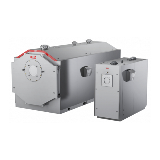
Page 6: System Layout
GENERAL INFORMATION GENERAL INFORMATION System layout TAU 2100 - 2600 N Burner Flame inspection window with pressure meas- urement fitting Door Body interior inspection flange Outlet Safety device fitting Heating return (high temperature) Combustion chamber Heating return (low temperature) 10 Flue gas box Flue gas exhaust 12 Inspection window 13 Condensate outlet... -
Page 7: Burner Combination
GENERAL INFORMATION GENERAL INFORMATION Burner combination BURNERS TAU N Burner flange Accessory MODEL CODE 2100 2600 as standard (compulsory) Standard GAS (yellow flame) ● (x) RS 250/M MZ Tc 3788410 20164364 ● RS 310/M MZ 20068351 20163867 RS 410/M MZ 20068361 20163867 LOW NOX GAS... - Page 8 GENERAL INFORMATION GENERAL INFORMATION IMPORTANT NOTES FOR BURNER INSTALLATION When you finish installing the burner in the boiler, fill the gap between the burner’s blast tube and the refractory ma- Before fixing the burner to the boiler, make sure that: terial in the door with the ceramic insulation (A) supplied −...
-
Page 9: Technical Specifications
GENERAL INFORMATION GENERAL INFORMATION Technical specifications TAU N DESCRIPTION 2100 2600 Device type Condensing boiler for central heating B23 - B23P (*) Fuel All GASES Device category See Burner 2331 2886 Rated heat input (Q max) GCV (NCV) kW max (2100) (2600) 1943,6... -
Page 10: System Manager
SYSTEM MANAGER SYSTEM MANAGER 2 SYSTEM MANAGER − Adjust the timer thermostat (if installed) or the tempera- ture control to the desired temperature (~20° C) Putting into service Have ’s Technical Assistance Service start up your TAU N boiler for the first time. Once this has been done, the boiler can be left to function automatically. -
Page 11: Preparing For Extended Periods Of Disuse
SYSTEM MANAGER SYSTEM MANAGER Preparing for extended periods of disuse Cleaning If the boiler is not going to be used for an extended period of Use a cloth damped in soapy water to clean the boiler’s external time, perform the following operations: casing. -
Page 12: Useful Information
SYSTEM MANAGER SYSTEM MANAGER Useful information Seller: ................Installer: ................Mr.: .................. Mr.: .................. Address: ................Address: ................Tel.: .................. Tel.: .................. Technical Assistance Service: ..........Mr.: .................. Address: ................Tel.: .................. Date Work done Fuel oil supplier: ............... Mr.: .................. Address: ................ -
Page 13: Installer
INSTALLER INSTALLER 3 INSTALLER The second package contains the panelling, complete with the assembly accessories, inside a protective cardboard box and a wooden crate. Unpacking the product For the boiler to function correctly, it must be connected to a The TAU N boiler is supplied in two separate packages. control panel and dedicated control accessories. -
Page 14: Overall Dimensions And Weights
INSTALLER INSTALLER Overall dimensions and weights TAU N DESCRIPTION 2100 2600 1750 1850 1800 1900 4020 4425 3612 4024 1945 2070 1870 2128 Net weight 4750 5550... -
Page 15: Handling
INSTALLER INSTALLER Handling MOVING WITH A HOIST Two lifting points (B) are provided for lifting with crane on the upper part of the boiler. Proceed as follows to move the boiler and remove the packaging: Before handling the appliance and removing the packaging, −... -
Page 16: Installation Premises
INSTALLER INSTALLER Installation premises TAU N steel boilers must be installed in a dedicated boiler For Belgium boilers must be installed according to the NBN room, with adequately sized vents, in compliance with applica- D51.003 standard, the NBN B61.001 standard (output > 70 ble laws and standards. -
Page 17: Positioning Of Sensor Sockets
INSTALLER INSTALLER Positioning of sensor sockets TAU 2100-2600 N TAU N 2100 2600 Length of the socket min. max. min. max. 1 - Flow sensor socket connector (1/2") 70mm 150mm 70mm 150mm 2 - Overtemperature protection (1/2") 120mm 190mm 120mm 190mm 3 - Return sensor socket connector (1/2") 120mm... -
Page 18: Water-Side Pressure Drop
INSTALLER INSTALLER 3.5.1 Water-side pressure drop Pressure drop [mbar] TAU N 2100 TAU N 2600 10 20 30 40 50 60 70 80 90 100 110 120 130 140 150 160 170 180 190 200 210 220 230 240 250 260 270 280 290 300 Flow-rate [m The curves refer to a density of 983,2 kg/m , a water temperature of +20°C and a kinematic viscosity of 0,474 mm... -
Page 19: Water In Central Heating Systems
INSTALLER INSTALLER Water in central heating systems 2.1 New central heating systems INTRODUCTION The system must be filled up slowly the first time; once it is filled and the air expelled it should never need to be topped up again. Water used in central heating systems MUST be suitably treated Systems should also be operated at maximum working tem- to ensure the correct functioning of those systems and to guar-... -
Page 20: Water Connections
INSTALLER INSTALLER Water connections Steel boilers TAU N are designed and built to be installed on heating systems and also for the production of domestic hot water if connected to suitable systems. The characteristics of the water fittings are shown in the table. The choice of system components and the method of their installation are left up to the installer. -
Page 21: Schematic Diagram
INSTALLER INSTALLER Schematic diagram Direct systems CENTRAL HEATING CENTRAL HEATING DHW USER RETURN SUPPLY POINT 3 15 16 INLET 15 3 Direct and mixed systems CENTRAL HEATING DHW USER SUPPLY POINT LT (*) HT (*) CENTRAL CENTRAL HEATING HEATING RETURN RETURN 15 16 INLET... - Page 22 INSTALLER INSTALLER Combination with multiple condensing boilers CENTRAL HEATING CENTRAL RETURN HEATING SUPPLY MAKE-UP WATER FLOW LT (*) RETURN COLD WATER INLET 16 3 FLOW LT (*) RETURN 16 3 FLOW LT (*) RETURN Boiler Water softener filter Burner Siphon Disconnect valves Condensate outlet Central heating system pump...
- Page 23 INSTALLER INSTALLER Two heating boilers and domestic hot water production HT (*) LT (*) CENTRAL CENTRAL CENTRAL HEATING HEATING HEATING SUPPLY RETURN RETURN MAKE-UP WATER 4 5 3 3 12 10 3 LOADING STORAGE TANK HT (*) FLOW RETURN LT (*) RETURN COLD WATER...
- Page 24 INSTALLER INSTALLER Combination with multiple boilers with primary and secondary circuit MAKE-UP WATER CENTRAL HEATING SUPPLY FLOW LT (*) RETURN LT (*) CENTRAL HEATING RETURN FLOW LT (*) COLD RETURN WATER INLET FLOW LT (*) RETURN Boiler Water softener filter Burner Siphon Disconnect valves...
- Page 25 INSTALLER INSTALLER Combination with multiple boilers and cascade sequence with motorised valve CENTRAL CENTRAL HEATING HEATING RETURN SUPPLY FLOW LT (*) RETURN COLD WATER INLET FLOW LT (*) RETURN FLOW LT (*) RETURN Boiler Water softener filter Burner Siphon Disconnect valves Condensate outlet Central heating system pump Boiler drain...
-
Page 26: Condensate Evacuation
INSTALLER INSTALLER Condensate evacuation 3.10 Neutralising the condensate TAU N condensing boilers produce a flow of condensate that TYPE N3 NEUTRALISATION KIT varies according to operating conditions. The maximum hourly The TYPE N3 neutralisation units were designed for systems production of condensate is shown in the technical specifica- equipped with the central heating plant condensate outlet trap tions table for each individual model. - Page 27 INSTALLER INSTALLER NEUTRALISATION UNIT TYPE HN3 (with pump) The connection pipes used must be as short and straight as The TYPE HN3 neutralisation units were designed for systems possible and corrosion-resistant. Any curves or sharp bends equipped with the central heating plant condensate outlet trap can lead to the hoses becoming clogged and can therefore located higher than the boiler condensate outlet.
-
Page 28: Discharge Of Combustion Products
øi at discharge RIELLO TAU N or neutralisation of condensate drain The stack must guarantee the minimum draught specified by applicable technical standards, assuming zero pressure at the connection to the flue gas exhaust. Inadequate or badly dimensioned stacks and flues can increase combustion noise and affect combustion parameters Joints must be sealed using suitable materials (e.g. -
Page 29: Door Hinges
INSTALLER INSTALLER 3.12 Door hinges − Remove the snap ring (2) and the through pin (3). − Unscrew the screws (4) and remove the support/centring The boilers are equipped with 4 hinge points to allow a rapid bracket (5). reversal of the door opening direction. −... -
Page 30: Earth Connection
INSTALLER INSTALLER 3.14 Earth connection Bottom hinge − Loosen the nuts (1). − Loosen the nut (2), unscrew and remove the through bolt For the earthing of the boiler body, a connection point is pro- (3). vided in the centre of the frame to be connected to an effective earthing system. -
Page 31: Fitting The Casing Panels
INSTALLER INSTALLER 3.15 Fitting the casing panels − Screw the four screws (used as fixing points) into the holes on the back of panels (7) and (8) (two per panel). To mount the panelling, proceed as follows: − Open the pre-cut slots on the side panel (3) or (4) (de- pending on which side you want to install the control panel), in correspondence with the “oval”... - Page 32 INSTALLER INSTALLER − Hook the upper rear panel (13) to the provided pins. − Fit the central rear panels (15, 16), inserting them from the sides to hook them to the upper and lower pins of the side panels. − Fit the front profile (17) by hooking it to the pins of the upper panels.
- Page 33 The labels can be found in the document pouch. The appliance installer MUST apply these labels, as shown in the figure below, once installation is complete. They must be visible. If the labels are lost, please request new ones from the Technical Assistance Service. RIELLO S.p.A. Via Ing.Pilade Riello 7 37045 Legnago (VR) - ITALY 066940IE CALDAIA IN ACCIAIO STEEL BOILER...
-
Page 34: Technical Assistance Service
TECHNICAL ASSISTANCE SERVICE TECHNICAL ASSISTANCE SERVICE 4 TECHNICAL ASSISTANCE SERVICE − The mains power connections to the boiler and its ac- cessories (burner, pump, control panel, thermostats, etc.) have been properly made. Preparing for initial startup It is essential to perform the following checks before starting up or testing the functioning of your TAU N boiler. -
Page 35: Checks During And After Initial Start-Up
TECHNICAL ASSISTANCE SERVICE TECHNICAL ASSISTANCE SERVICE The burner should now ignite and remain in operation until the Turn off the main power switch to the boiler and make sure that set temperature is reached. the boiler shuts down properly. If any ignition faults or malfunctions occur, the burner performs a “LOCKOUT SHUTDOWN”. -
Page 36: Maintenance
TECHNICAL ASSISTANCE SERVICE TECHNICAL ASSISTANCE SERVICE 4.4 Maintenance Adjusting the door Regular maintenance is a legal requirement. It is also essen- Make quite sure that the door presses uniformly all around the tial for the safety, efficiency and durability of the boiler. Prop- double seal to prevent dangerous fumes escaping into the air er maintenance keeps consumption and emissions down, and from the pressurised furnace. - Page 37 TECHNICAL ASSISTANCE SERVICE TECHNICAL ASSISTANCE SERVICE Before proceeding with the adjustment of the door: Door balancing − Check that the pin (1)on the door slides freely in the cen- tre of the slot on the support/centring bracket (B). − Check that the door profile (2) rests on the support/cen- tring bracket (B), If one of these two conditions is not met, proceed with the ad- justment operations described on the following pages.
- Page 38 TECHNICAL ASSISTANCE SERVICE TECHNICAL ASSISTANCE SERVICE Door height adjustment Door seal adjustment − Loosen the nut (8)of the lower hinge and adjust the ver- − Loosen the screws (10) of the upper and lower hinge and tical alignment of the door opening/closing by turning adjust the position of the door until the gaskets start to the screw (9).
- Page 39 TECHNICAL ASSISTANCE SERVICE TECHNICAL ASSISTANCE SERVICE − Fully tighten the door locking bolts (A), using a 27 mm hexagonal socket wrench. Make sure that there are no leaks around the boiler door seal. If you detect any leakage of fumes, increase the tight- ening of the door fixing bolts.
-
Page 40: Cleaning The Boiler
TECHNICAL ASSISTANCE SERVICE TECHNICAL ASSISTANCE SERVICE 4.6 Cleaning the boiler − Remove the residues removed from the flue gases cham- ber through the inspection openings (4). If more thorough cleaning is needed: DANGER: Risk of death due to electric shock! −... -
Page 41: External Cleaning
TECHNICAL ASSISTANCE SERVICE TECHNICAL ASSISTANCE SERVICE External cleaning The boiler must be completely emptied if the rear inspection door (2) has to be opened. The external panels of the boiler and control panel must be Check the state of wear of the gaskets and replace them if nec- cleaned using cloths moistened with soap and water. -
Page 42: Troubleshooting
TECHNICAL ASSISTANCE SERVICE TECHNICAL ASSISTANCE SERVICE Troubleshooting FAULT CAUSE SOLUTION Boiler dirty − Clean the flue gas pipes Heat exchanger and burner mismatched − Check specifications and settings The boiler does not reach its temperature setpoint Burner capacity insufficient − Check and adjust the burner −... - Page 43 TECHNICAL ASSISTANCE SERVICE TECHNICAL ASSISTANCE SERVICE...
- Page 44 RIELLO S.p.A. Via Ing. Pilade Riello, 7 37045 - Legnago (VR) www.riello.com The manufacturer strives to continuously improve all products. Appearance, dimensions, technical specifications, standard equipment and accessories are therefore liable to modification without notice.
Need help?
Do you have a question about the TAU 2100 N and is the answer not in the manual?
Questions and answers