
Related Manuals for IMG STAGELINE AKB-210DSP


Summary of Contents for IMG STAGELINE AKB-210DSP
- Page 1 Active Speaker Module with DSP Technology AKB-210DSP Bestellnummer 38.0220 INSTRUCTION MANUAL ELECTRONICS FOR SPECIALISTS ELECTRONICS FOR SPECIALISTS ELECTRONICS FOR SPECIALISTS ELECTRONICS FOR SPECIALISTS...
-
Page 2: Table Of Contents
User manual revision 5 Table of contents Product description ..........................3 Type remarks ............................3 Key features ............................3 Applications............................4 Connections............................5 System information ..........................7 Description ............................7 Hardware Architecture......................... 8 Digital audio input..........................8 Audio performance data........................8 Remote control ............................. -
Page 3: Product Description
User manual revision 5 Product description Type remarks The first time the is used all biquads are zero, so there are no filters installed. Connecting any speakers and audio input at this point may cause some damage to them. Take notice on what changes you make, changing a 2channel filters to flat can damage your speakers because both channels may be full range! After updating the firmware please be sure to also download the latest version of the manual from our website... -
Page 4: Applications
User manual revision 5 Applications With one module the following applications can be set up, further explained in the “Hardware part” chapter: Stereo passive filtered system Briged mode for single subwoofer (max 140Watt short term into 8 Ohms) Mono/mid 2 way setup (tweeter + sub) When two modules are used the following applications can be set up, also explained in “Hardware part”: 2 way active filtered stereo system... -
Page 5: Connections
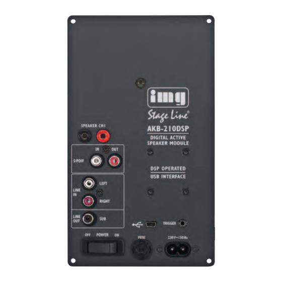
User manual revision 5 Connections Figure 1 Overview of the connections on the front of the Function un i Amplifier output, for slave speaker in stereo setup Analogue input left channel Analogue input right channel Subwoofer output 7 7 7 7 On/Off switch 8 8 a USB control input... - Page 6 User manual revision 5 9 9 9 9 Master trigger output, slave trigger input Right channel trough 1 1 1 0 Main Fuse 1 1 1 ~230 volt input Digital version only: 2 2 2 2 SPDIF audio input SPDIF audio output Audio trough for slave module 8 8 b USB audio input...
-
Page 7: System Information
User manual revision 5 System information Figure 3 Description is a plate amp for use in powered speaker systems. As an active speaker controller, a can form the basis of a powerful active two way monitor. In stereo mode will power an active master / passive slave pair. Finally, the module may also be used as a one way 140W amplifier. -
Page 8: Hardware Architecture
User manual revision 5 Hardware Architecture The standard version of the has a stereo analogue audio input. This analogue signal is converted to digital, processed by the DSP and then converted back to analogue. A microcontroller controls the DSP, reads the control panel and communicates with the PC and/or another that may be attached. -
Page 9: Remote Control
User manual revision 5 Remote control The master unit is fitted with small keypad which can be placed in the front of the loudspeaker cabinet. Volume and idle/on is controlled by the pushbuttons and by an infra red remote control. When 2 modules are used only one control panel is needed, cause the trigger communication between master and slave. -
Page 10: Hardware Part
User manual revision 5 Figure 4 4 Figure Hardware part Stereo setup: Connect the module to your pc by a USB cable and select on witch side of the room your master module will be, the speaker with the . When your master is the left channel the slave will become the right channel. - Page 11 User manual revision 5 Bridged setup: Connect the module to your pc by a USB cable and select where the master module is placed, master module is left or right audio or functions as a sub woofer. When you use 2 for a stereo bridged setup you will also have to initialise the second (slave) module, see example in the last chapter of this document.
-
Page 12: Sub Out
User manual revision 5 Sub-out On all setups there is also the ability to use the Line out sub. This can source an active subwoofer module. The sub output has up to 6 biquads for filtering that can exclude the use of an external subwoofer filter. -
Page 13: Software Installation
User manual revision 5 Software installation System requirements: Pentium class or higher • 64MB RAM • USB1.0 or higher • All files are compressed in the setup.zip file. This zip file contains a DLL file for communication and a .EXE file, which represents the DSP filter design program. -
Page 14: Input Options
User manual revision 5 as the standard source. During analogue in the other two inputs are scanned for any valid signal. The first channel that contains any valid audio is selected and becomes the new input source. But if you put in the USB cable but you want to use the analogue input you can force the analogue input to be used. -
Page 15: Filter Design
User manual revision 5 Filter design When you want to make some filters for your module they can be designed in the “Filter design”. Under view there can be switched between the control panel and the filter design window. The following pages will give you a widespread instruction possibilities of the program. -
Page 16: Graph Area
User manual revision 5 Graph Area The magnitude tab shows the imported driver responses, filters, individual biquads, individual filtered driver responses and the sum. Colour Function Blue, thin Measured woofer response Green, thin Measured midrange response Red. thin Measured tweeter response Blue, thick Filtered woofer response Green, thick... -
Page 17: Settings Window
User manual revision 5 Settings window The settings window is under File > Settings… Measurement sampling rate sets the sample rate used in the imported response files (typically 48kHz). Processor sampling rate is that of the DSP hardware. Note that this setting does not control the sampling rate of the hardware. - Page 18 User manual revision 5 Figure 1 1 1 2 Figure The first echo is apparent at 5ms. Zoom in until you see only the anechoic portion of the impulse response. Dragging the mouse, left button down, from left to right marks a zoom area. Dragging from right to left zooms out.
- Page 19 User manual revision 5 Figure 1 1 3 Click “truncate”. Anything currently outside the display is drawn in grey and not processed. You will notice that in the frequency graph a portion of the low frequency response is also drawn in grey. This is to remind the user that insufficient information is available to make *any* correction below this frequency.
-
Page 20: Designing Filters
User manual revision 5 Designing filters Biquad function Parameters Unity Section is not used LPF1 Cut off frequency (always 3dB) First order lowpass LPF2 Cut off frequency (asymptotically) Second order lowpass. A Q of 0.71 corresponds to butterworth. 0.5 corresponds to LR2. Two identical sections with a Q of 0.71 form an LR4 filter. -
Page 21: Download
User manual revision 5 As a rule of thumb, sharp dips are diffraction artefacts while sharp peaks are caused by the drivers themselves. Exceptions are room resonances (if the response is not correctly truncated) and diffractions on repetitive patterns. The second step is designing the actual crossover filters. All the usual strategies work. Delaying higher frequency drivers with respect to lower frequency ones is a powerful alternative to using asymmetric slopes and yields substantially improved coherence through the crossover region. - Page 22 User manual revision 5 Figure 1 1 4...
-
Page 23: Examples
User manual revision 5 Examples Example 1: 2-channel stereo setup This example will guide you through setting up you 2 channel stereo system with the schematic presentation of similar setup is given in Figure 6. The master module is always the one with the control panel connected. - Page 24 User manual revision 5 Figure 1 1 6 11. When download is completed you can power down the module 12. Start with the SLAVE module S S S lave Slave Start the pc program, filter design. Or go back to the control panel (ctrl+c) if the program is still running Plug in the power connector and switch the module to ON Plug in the USB cable (assumed that you’ve already installed the software as...
-
Page 25: Example 2: Stereo Setup With Active Subwoofer
User manual revision 5 When download is completed you can power down the module and disconnect the USB cable Master and Slave are now set up as a 2 channel stereo system F n l s Final setup When both modules are installed it is time to complete your setup. First connect your speakers as explained in chapter Product overview Connect the trigger cable (mini jack) or or SPDIF cable between both modules, depending on the used audio source... - Page 26 User manual revision 5 Software installation” ) Wait for automatic connection, a popup is displayed as in Figure 8. If connection is not automatic the press the “connect” button. If there is no response there is a problem with the USB connection or your operating system that can not detect the USB device Set the system to the desired setup, for this example stereo left because the left speaker holds the...
-
Page 27: Technical Data
User manual revision 5 Technical data Supply voltage 230Volt AC/50Hz +/ 10% Dimensions 115mmx200mmx60mm (WxHxD) Plate thickness 2,5mm Weight 1,5 kg Clearance...
Need help?
Do you have a question about the AKB-210DSP and is the answer not in the manual?
Questions and answers