Advertisement
Available languages
Available languages
Quick Links
For additional safety instructions, read Safety Instruction book No. 58-13-0000.
Sound and Vibration information.
•
Typically the A-weighted sound pressure level of the tool is less than 82 dB (A). The noise level when working can exceed 95 dB (A). Wear ear protection!
•
The typical weighted acceleration is less than 2,5 m/s
These declared values were obtained by laboratory type testing in compliance with the stated standards and are not adequate for use in risk
assessments. Values measured in individual work places may be higher than the declared values. The actual exposure values and risk of harm
experienced by an individual user are unique and depend upon the way the user works, the work piece and the workstation design, as well as upon
the exposure time and the physical condition of the user.
We, XYZ Electric Tool Corp., cannot be held liable for the consequences of using the declared values, instead of values reflecting the actual
exposure, in an individual risk assessment in a work place situation over which we have no control.
Symbology
Alternating Current
CE Conformity Mark
SEMKO Safety Mark
No Load Revolutions per Minute (RPM)
watts
Australian C-tick Mark
DANGER! To reduce the risk of injury, always
keep hands, rags, clothing, etc. away from
moving parts and chips. Do not try to remove
chips while the cutter is rotating. Chips are
sharp and can pull objects into moving parts.
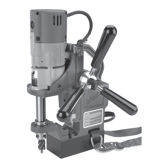
A
1
-
Drill motor
2
-
Slide
3
-
Wrench storage
4
-
Stop knob
5
-
Pinion
6
-
Hub
7
-
Handle screw
8
-
Feed handle
9
-
Grip
10 -
Housing
11 -
Cord
English
Compact Electromagnetic Drill Press
Catalog
Article
No.
No.
MDE 38
4270-50
220-240
Compact
.
2
12 -
Safety strap
13 -
Magnetic base
14 -
Spacer
15 -
Drill spindle
16 -
Support bracket
17 -
Cutting fluid reservoir
18 -
Control panel
19 -
Magnet indicator light
20 -
Magnet switch
21 -
Drill on/off switch
22 -
Hand pump
Specifications
No Load
Volts
Watts
RPM
AC
400
450
Assembly
B
Attaching Feed Handles and Grips
1.
Attach the feed handles and grips to the hub. Tighten securely.
2.
Mount the hub to either side by aligning the two (2) dowel pins on the
hub with the holes in the pinion. Tighten the handle screw.
C
Stop Knob
23 -
The stop knob stops the slide from moving. To install, screw the stop
knob into the location shown.
D
Adjusting the Gib Assembly
To adjust the gib, loosen or tighten the gib adjustment set screws on the
side of the housing accordingly with the 3/32" hex key pr ovided.
Tightening the set screws increases friction on the slide. The gib should
be set tight enough to support the weight of the drill in any position. All
adjustment set screws should be set to provide smooth and even travel
over the entire length of slide movement.
The set screws contain a nylon patch that prevents them from moving
freely. Additional adjustment of the gib may be required over time with
extended use of the tool.
E F
24 - Spacer
25 - Support bracket
This unit is shipped from the factory set for 1" depth cutters (Fig. E).
When using 2" depth cutters, install the support bracket with the spacer
on bottom (Fig. F).
NOTE: Do not use a spacer and support bracket with a chuck adapter.
2
Arbor
T wi st
Cutt er
Bore
Drill
19 mm
38 mm
13 mm
Stop knob
Adjusting the Support Bracket and Spacer for
Depth of Cut
HSS
Advertisement

Related Manuals for Milwaukee MDE 38 Compact


Summary of Contents for Milwaukee MDE 38 Compact
- Page 1 Compact Electromagnetic Drill Press Specifications No Load Arbor Catalog Article Volts T wi st Cutt er Watts Bore Drill 19 mm 38 mm MDE 38 4270-50 220-240 13 mm Compact For additional safety instructions, read Safety Instruction book No. 58-13-0000. Sound and Vibration information.
-
Page 2: Operation
Features WARNING! To reduce the risk of injury, always use a safety strap when drilling Line Lockout overhead or on a vertical surface. The line lockout prevents the drill motor from starting when line power is first applied to the system or after a momentary power loss. To reset tool, turn magnet switch to "OFF"... -
Page 3: Maintenance
Maintenance 10. K eep constant pressure throughout the entire operation to prevent chips and burrs from falling under the cutting edges. Cutting debris under cutter m ake cutting difficu lt WARNING! impossible. To reduce the risk of personal injury and damage, never immerse 11. - Page 4 Engenho de Furar Electromagnético Compacto Especificações Ferramenta de corte Nº de Broca R.P.M. Diâmetro de aço rápido catálogo helicoidal Ref. Watts em vazi o do fuso V ac MDE 38 38 mm 4270-50 13 mm 220-240 19 mm Compacto Para instruções de segurança adicionais, consultar as Instruções sobre Segurança, ref. 58-13-0000. Informação sobre Ruído e Vibrações.
- Page 5 Características Deslocar o fuso da máquina para cima, de modo a afastar a ferramenta Sistema de inibição de arranque de corte e a cavilha central da superfície de trabalho. O sistema de inibição de arranque destina-se a impedir o arranque do ATENÇÃO! motor da ferramenta, quando a corrente de alimentação é...
- Page 6 Manutenção ATENÇÃO! ATENÇÃO! Para reduzir o risco de lesões corporais e danos materiais, não Com uma força excessiva, o íman liberta-se da peça de trabalho. mergulhar a ferramenta, a bateria ou o carregador em qualquer tipo de líquido, nem permitir a infiltração de líquidos nos mesmos. 9.