Table of Contents
Advertisement
18-HD82D1-1B-EN
Nexia Smart Home
Comfort System
Customer Service:
For HVAC related
issues, contact your
servicing dealer
Î NOTE: A 24 Volt
common and hot
wire MUST be
connected to
the XR724 for
Contents
User Guide
Features ............................................................................................................................. 2
Operation ............................................................................................................................ 3
User Settings ....................................................................................................................... 4
Schedules ........................................................................................................................... 5
Display settings .................................................................................................................. 5
Sensor Settings ................................................................................................................... 5
Wifi settings ....................................................................................................................... 6
Nexia settings ..................................................................................................................... 6
Installer Settings .................................................................................................................. 7
Test Mode ........................................................................................................................... 7
Reminders .......................................................................................................................... 8
Restore Defaults ................................................................................................................. 8
About .................................................................................................................................. 8
Clean Screen ...................................................................................................................... 8
Nexia Mobile App Instructions ............................................................................................ 9
Installer's Guide
Product Specifications ..................................................................................................... 16
Installation And Wiring ..................................................................................................... 17
Physical Location ............................................................................................................. 17
Field Wiring Diagrams ...................................................................................................... 18
Remote Temp Sensors ..................................................................................................... 35
Troubleshooting ................................................................................................................ 37
Fcc/Ic Notice ................................................................................................................... 38
XR724
Touchscreen
Comfort Control
Model TCONT724AS42DA
User Guide and Installation Instructions
Advertisement
Table of Contents

Summary of Contents for Trane NEXIA XR724
- Page 1 18-HD82D1-1B-EN XR724 Touchscreen Comfort Control Model TCONT724AS42DA User Guide and Installation Instructions Nexia Smart Home Comfort System Customer Service: For HVAC related issues, contact your servicing dealer Î NOTE: A 24 Volt common and hot wire MUST be connected to the XR724 for operation.
- Page 2 XR724 USER GUIDE XR724 Features • WiFi comfort control • Remote access via smartphone, tablet, or P.C. (requires a Nexia Smart Home Comfort System account) • Interactive 4.3” black & white touchscreen • 7 Day programmable, 4 schedules/day • Built in humidity sensor with RH display •...
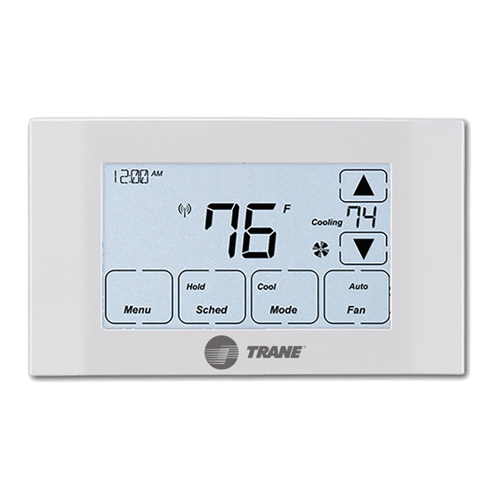
- Page 3 XR724 USER GUIDE Operation The XR724 Comfort Control provides typical operation of a forced air heating and cooling HVAC system. It also features WiFi capability for remote control and Nexia Smart Home Comfort System connectivity. Cooling Hold Cool Auto Menu Sched Mode Normally, the Comfort Control displays the Home Screen as shown above.
- Page 4 XR724 USER GUIDE MENU OPTIONS The following is a guide of the menu options available by pressing the Menu button. Certain menu selections, which are marked by an asterisk ( * ), may or may not be present depending on other menu settings. HUMIDITY * * Only appears as a menu item if Dehumidify is set to Yes, Aux Relay is set to Dehumidifier, or Aux Relay is set to Humidity.
- Page 5 XR724 USER GUIDE USER SETTINGS continued The following is a guide of the menu options available by pressing the Menu button. Certain menu selections, which are marked by an asterisk ( * ), may or may not be present depending on other menu settings. SCHEDULES Setting Range / Sub Settings...
- Page 6 XR724 USER GUIDE WIFI Even though open networks (no password) and WEP WiFi encryption are supported, it is recommended to use a more secure network encryption such as WPA2 or later. WIFI Setting Range Description Network Join a Network Network connection action required: Yes, No OR leave network Status WiFi not configured...
- Page 7 XR724 USER GUIDE The following is a guide of the menu options available on screen accessed by pressing the Menu button. Certain menu selections, which are marked by an asterisk ( * ), may or may not be present depending on other menu settings. SERVICE Press and hold Service button for 5 seconds until service menu is displayed INSTALLER SETTINGS...
- Page 8 XR724 USER GUIDE SERVICE continued The following is a guide of the menu options available on screen accessed by pressing the Menu button. Certain menu selections, which are marked by an asterisk ( * ), may or may not be present depending on other menu settings. TEST MODE (stays on for 30 minutes) Test Mode...
- Page 9 XR724 USER GUIDE CLEAN SCREEN Setting Range Description Clean Screen Yes, No 30 sec countdown Once all selections have been made, press the Done button to exit and return to menu. Press Next to navigate to the next setting. XR724 Control Response Profiles From Installer Settings / Comfort Settings (numbers are in degrees, F or C) Cooling Normal...
- Page 10 XR724 USER GUIDE XR724 NEXIA Enrollment The XR724 uses the Nexia mobile app to enroll into Nexia. To enroll download the Nexia app from the Google Play ™ Store or App Store , then launch the app. Once in the app, click Connect New Device, select 724 thermostat then ®...
- Page 11 XR724 USER GUIDE XR724 NEXIA Enrollment continued Even though open networks (no password) and WEP WiFi encryption are supported, it is recommended to use a more secure network encryption such as WPA2 or later. 18-HD82D1-1B-EN...
- Page 12 XR724 USER GUIDE XR724 NEXIA Enrollment continued 18-HD82D1-1B-EN...
- Page 13 XR724 USER GUIDE XR724 NEXIA Enrollment continued XR724 Nexia WiFi Reconfiguration PRESS PRESS 18-HD82D1-1B-EN...
- Page 14 XR724 USER GUIDE XR724 Nexia WiFi Reconfiguration continued 18-HD82D1-1B-EN...
- Page 15 XR724 USER GUIDE XR724 Nexia WiFi Reconfiguration continued 18-HD82D1-1B-EN...
- Page 16 XR724 USER GUIDE XR724 Nexia WiFi Reconfiguration continued 18-HD82D1-1B-EN...
- Page 17 XR724 USER GUIDE XR724 Nexia WiFi Reconfiguration continued 18-HD82D1-1B-EN...
- Page 18 XR724 INSTALLER’S GUIDE INSTALLATION AND WIRING MERCURY NOTICE When this Comfort Control is replacing an old thermostat that contains mercury in a sealed tube, do not dispose of your old thermostat in the trash. Dispose of properly. Contact your local waste management authority for instructions regarding recycling and proper disposal of the old thermostat.
- Page 19 XR724 INSTALLER’S GUIDE CAUTION: ELECTRICAL HAZARD CAUTION: Before proceeding with installation, verify system power has been removed. Separate the face of the new Comfort Control from the wall plate. Î NOTE: It is not recommended that this WiFi Comfort Control be mounted onto metal structures.
- Page 20 XR724 INSTALLER’S GUIDE Field Wiring Diagrams Heat/Cool Wiring Diagrams Heat/Cool Diagram 1: 1 or 2 Stage Cooling w/TAM7 Model Variable Speed Air Handler or TAM9 24V mode One or Two Stage VS Air Handler & Cooling Only Electric Heat Thermostat Connection Remote (Note 2) Sensor...
- Page 21 XR724 INSTALLER’S GUIDE Heat/Cool Wiring Diagrams Heat/Cool Diagram 3: 1 Stage Cooling w/“GAM5B” Model Air Handler One Stage Non-VS Cooling Only Air Handler & Thermostat Connection Electric Heat Remote Sensor Outdoor Sensor (Note 1) Aux relay outputs (Note 2) Remote Temperature Sensor Connections and Operation: Notes: Sensor Options in the Installer Settings/Sensor Settings menu 1.
- Page 22 XR724 INSTALLER’S GUIDE Heat/Cool Wiring Diagrams Heat/Cool Diagram 5: 1 Stage Cooling w/GAF2-S Model Air Handler One Stage Non-VS Cooling Only Air Handler & Thermostat Connection Electric Heat Remote Sensor Outdoor Sensor Aux relay outputs Remote Temperature Sensor Connections and Operation: Sensor Options in the Installer Settings/Sensor Settings menu Remote Sensor (connect to the RS terminals) - None...
- Page 23 XR724 INSTALLER’S GUIDE Heat/Cool Wiring Diagrams Heat/Cool Diagram 7: 1 Stage Cooling w/GAT2 & GAM2 Model Air Handlers One Stage Non-VS Cooling Only Air Handler & Thermostat Connection Electric Heat Remote Sensor Outdoor Sensor (Note 1) Aux relay outputs Notes: Remote Temperature Sensor Connections and Operation: 1.
- Page 24 Outdoor Temp Sensor (connect to the ODT terminals) 3. Jumper “W2” to “W3” if three stages of indoor heat are available - None 4. For non-Trane/American Standard Indoor units “BK” is not - Outdoor connected and “Y1”/”Y2” must be connected at indoor unit.
- Page 25 2. “Y2” & “R” connections at outdoor are only required for two - None stage units - Replaces internal sensor 3. For non-Trane/American Standard Indoor units “BK” is not - Average with internal sensor connected and “Y1”/”Y2” must be connected at indoor unit. Outdoor Temp Sensor (connect to the ODT terminals)
- Page 26 Outdoor Temp Sensor (connect to the ODT terminals) stage systems - None 3. For non-Trane/American Standard Indoor units “BK” is not - Outdoor Caution: Do not run sensor wires in the same bundle with HVAC connected and “Y1”/”Y2” must be connected at indoor unit.
- Page 27 1. Cut/remove the factory installed “BK” jumper on the Sensor Options in the Installer Settings/Sensor Settings menu ECM fan control board Remote Sensor (connect to the RS terminals) 2. For non-Trane/American Standard Indoor units “BK” is - None not connected - Replaces internal sensor...
- Page 28 XR724 INSTALLER’S GUIDE Heat Pump Wiring Diagrams Heat Pump Diagram 1: 1 or 2 Stage Heat Pump w/TAM7 Model Variable Speed Air Handler One or Two stage Variable Speed Air Thermostat Connection Heat Pump Handler & Electric Heat Remote Sensor Outdoor Sensor (Note 2)
- Page 29 XR724 INSTALLER’S GUIDE Heat Pump Wiring Diagrams Heat Pump Diagram 3: 1 Stage Heat Pump w/GAM5B Model Air Handler One stage Non-VS Air Thermostat Connection Heat Pump Handler & Electric Heat Remote Sensor Outdoor Sensor (Note 1) Aux relay outputs (Note 2) Notes: Remote Temperature Sensor Connections and Operation:...
- Page 30 XR724 INSTALLER’S GUIDE Heat Pump Wiring Diagrams Heat Pump Diagram 5: 1 Stage Heat Pump w/GAF2-S Model Air Handler One stage Non-VS Air Handler Thermostat Connection Heat Pump & Electric Heat Remote Sensor Outdoor Sensor Aux relay outputs Remote Temperature Sensor Connections and Operation: Sensor Options in the Installer Settings/Sensor Settings menu Remote Sensor (connect to the RS terminals) - None...
- Page 31 XR724 INSTALLER’S GUIDE Heat Pump Wiring Diagrams Heat Pump Diagram 7: 1 Stage Heat Pump w/GAT2 & GAM2 Model Air Handler One stage Non-VS Air Handler Thermostat Connection Heat Pump & Electric Heat Remote Sensor Outdoor Sensor (Note 1) Aux relay outputs Remote Temperature Sensor Connections and Operation: Sensor Options in the Installer Settings/Sensor Settings menu...
- Page 32 2. Jumper “W2” to “W3” if three stages of indoor heat - Average with internal sensor are available Outdoor Temp Sensor (connect to the ODT terminals) 3. For non-Trane/American Standard indoor units “BK” is not - None connected and the “Y1”/”Y2” must be connected at indoor unit - Outdoor Caution: Do not run sensor wires in the same bundle with HVAC wires.
- Page 33 1. Cut/remove the factory installed “BK” jumper on the ECM fan - Replaces internal sensor control board - Average with internal sensor 2. For non-Trane/American Standard indoor units “BK” is not Outdoor Temp Sensor (connect to the ODT terminals) connected - None...
- Page 34 Sensor Options in the Installer Settings/Sensor Settings menu 1. Cut/remove the factory installed “BK” jumper at the indoor unit Remote Sensor (connect to the RS terminals) 2. For non-Trane/American Standard Indoor units “BK” is not - None connected and “Y1”/”Y2” must be connected at indoor unit.
- Page 35 - None - Outdoor 3. For non-Trane/American Standard indoor units “BK” is not Caution: Do not run sensor wires in the same bundle with HVAC connected and “Y1”/”Y2” must be connect at indoor unit wires. Keep away from high voltage wiring to avoid interference.
- Page 36 1. Cut/remove the factory installed “BK” jumper on the Sensor Options in the Installer Settings/Sensor Settings menu ECM fan control board Remote Sensor (connect to the RS terminals) 2. For non-Trane/American Standard Indoor units “BK” - None is not connected - Replaces internal sensor 3.
- Page 37 XR724 INSTALLER’S GUIDE Optional Remote Temperature Sensor Installation Wire specification for remote sensors: 2 conductors, 18 gauge wire. Make sure that the sensor wires are installed in a separate cable from the wiring to the HVAC system. Best results for distances of 100 feet or less. Accuracy may be affected for distances up to a maximum of 200 feet.
- Page 38 XR724 INSTALLER’S GUIDE Troubleshooting Troubleshooting Symptom Possible Cause Action Display will not come on Loss of 24VAC between R & C at the Control 1) Check wiring between R & C 2) Check transformer for 24VAC output 3) Check for broken or shorted thermostat wire Indoor Temperature 1) Indoor temperature display needs calibrating 1) Calibrate indoor temperature sensor...
- Page 39 FCC NOTICE INFORMATION TO USER This device complies with Part 15 of the FCC Rules. Operation is subject to the following two conditions: (1) This device may not cause harmful interference, and (2) This device must accept any interference received, including interference that may cause undesired operation.
- Page 40 6200 Troup Highway File number 18-HD82D1-1B-EN Tyler, TX 75707 Supersedes www.trane.com Date 08/30/19 Trane has a policy of continuous product and product data improvement and it reserves the right to change © 2019 Trane U.S. Inc. design and specifications without notice.
Need help?
Do you have a question about the NEXIA XR724 and is the answer not in the manual?
Questions and answers
Why do I have to reset the thermostat whenever I have a power interruption?