
Subscribe to Our Youtube Channel
Related Manuals for Observator Instruments OMC-150


Summary of Contents for Observator Instruments OMC-150
- Page 1 Manual OMC-150 Version: 2.13 Status: Final Date: 25 October 2019 Author: Observator www.observator.com Manual | OMC-150 Page 1 | 38 Status: Final | Not confidential V2.13...
- Page 2 V2.08 Update CE declaration 2016-12-1 V2.09 Update maintenance section 2017-5-1 V2.10 Update EU declaration 2019-1-2 V2.11 Update IP rating 2019-2-1 V2.12 Update DoC 2019-10-25 V2.13 Update DoC & style Manual | OMC-150 Page 2 | 38 Status: Final | Not confidential V2.13...
- Page 3 Preface This manual provides information for the best performance and safe application of the OMC-150 anemometer. This manual is intended for the engineers who are responsible for site planning, installation, commissioning and maintenance of the intrinsically safe OMC-150 anemometer. Professional knowledge on mechanical and electrical systems in potentially explosive atmospheres is required for the users of this manual.
- Page 4 Manual | OMC-150 Page 4 | 38 Status: Final | Not confidential V2.13...
-
Page 5: Table Of Contents
Measurement of wind speed ......................10 Measurement of wind direction ......................10 Safety ..........................11 Safety measures by the design of the OMC-150 anemometer ............11 System integration - interconnection to the other system components ..........11 Required personnel qualification and remaining risks ..............12 Handling, transportation and storage ................13... - Page 6 End of operational life ....................23 Appendix A: Typical system layout ..................24 Appendix B: OMC-150 Specifications ..................26 Appendix C: Drawings ......................27 Appendix D: Spare Parts ......................30 Appendix E: OMC-150 Marking ....................31 Appendix F: ATEX certificate ....................32 Appendix G: IECEx certificate ....................34 Appendix H: EU Declaration of Conformity ................37...
-
Page 7: Introduction
Introduction Utilisation The OMC-150 anemometer is designed to measure wind speed and wind direction in harsh environments including potentially explosive atmospheres. Typical application areas are offshore industry, petrochemical industry, and transportation. All exposed parts are made in non-corrosive materials, therefore the OMC- 150 anemometer is ultimate suitable for marine environment. -
Page 8: Basic Specifications
1.5 Conditions of use. The OMC-150 anemometer is built to provide reliable measurement results under all weather conditions. Rain, snow, or other kinds of precipitation do not effect the readings. Further the OMC-150 anemometer is insensitive to noise, extreme temperatures, solar radiation, etc. -
Page 9: Description
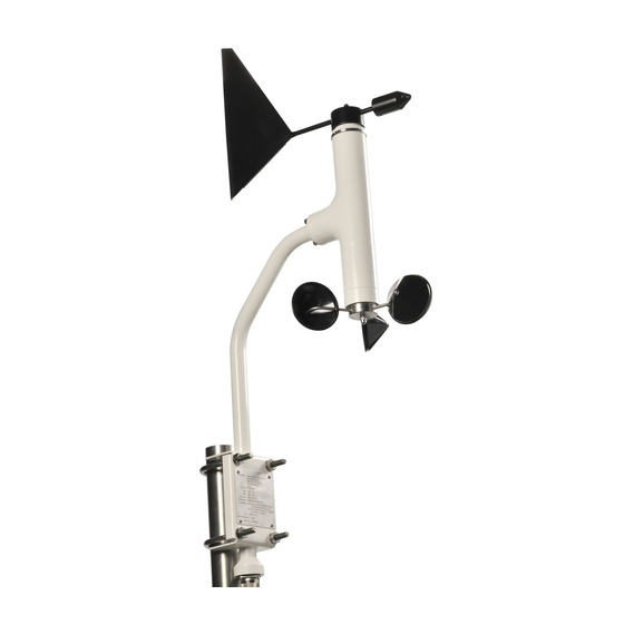
The OMC-150 anemometer consists of a sensor body and a mounting bracket. Note that the mounting bracket, though it is sometimes referred to as OMC-157, is an integral part of the OMC-150 anemometer. The mounting bracket has a mast clamp and an electrical plug connector. This clamp is designed for mounting on a vertical pipe end. -
Page 10: Operation
See Appendix A: for a typical system layout. Note that the maximum length of the field cable, which runs from the junction box (nearby the OMC-150 anemometer) through the Ex zone to the OMC-158-2 interface unit, is up to 1 km (depending on the cable quality). -
Page 11: Safety
The OMC-150 anemometer is a Category 2 G device, certified for use in potential explosive atmospheres (gas explosion) in zone 1 and zone 2. The method of protection of the OMC-150 anemometer is intrinsic safety (Ex-i) according to EN-60079-0 and EN-60079-11. A risk analysis was performed on the mechanical construction of the instrument, both for operation during normal use and for anticipated faults, according to EN13463-1. -
Page 12: Required Personnel Qualification And Remaining Risks
The engineers that are handling the OMC-150 anemometer at the point of installation must be aware of the risks of working at height. Local Safety regulations on site must be adhered to. Adequate Personal Protective Equipment must be used where necessary. -
Page 13: Handling, Transportation And Storage
Once the installed, store the packing for later use (see section 5.3) 5.2 Long term storage When not in use, store the OMC-150 anemometer in a dry place. Note that this is required, as the system is only weatherproof when mounted in an upright position while the electrical plug is mated. -
Page 14: Installation
Ensure that the OMC-150 anemometer will be mounted on a location that is free from turbulence from obstacles. Plan the OMC-150 anemometer in a free area as far as practicable. For guidance on the best location refer to the WMO CIMO Guide . -
Page 15: Assembly Of Cup And Vane
(this may not always possible) The shafts of the OMC-150 anemometer and the inside of the cup unit and vane unit are conical. This enables fastening of the capped nut without the shaft turning along. -
Page 16: Alignment Of The Wind Vane
North by rotating the complete mast, thus aligning the wind vane to the North. Note that the accuracy of the wind direction reading of the OMC-150 anemometer depends fully on the alignment of the vane! -
Page 17: Electrical Installation
6.7 Electrical installation Connections The OMC-150 anemometer is provided with a plug to connect the sensor (through a junction box) to the field cabling. The anemometer has a 7-core signal cable with common screen wired to the plug. connector sensor internal... -
Page 18: Commissioning
Commissioning Commissioning procedure It is impossible to calibrate the OMC-150 anemometer in the field. However, the following procedure makes sure that the installation was successful. 1) Check the connections 2) Install the interface and (if applicable) the display instrument. Normally the OMC-150 anemometer is powered through the interface unit. -
Page 19: Faults, Support, And Service
OMC- speed too low (not too slow location of the OMC-150 150 anemometer if zero) anemometer (any obstacles?) necessary mechanical problem; Contact check the sensor for dirt and... -
Page 20: Support, Service And Warranty
2984BM Ridderkerk The Netherlands Tel. + 31 180 463 411 Fax + 31 180 463 530 http://www.observator.com Purchase of replacements: sales@observator.com Technical support: service@observator.com Service and warranty: service@observator.com Manual | OMC-150 Page 20 | 38 Status: Final | Not confidential V2.13... -
Page 21: Maintenance
Take care not to damage the cup unit or the vane blade while mounting or disassembly. The shafts of the OMC-150 anemometer and the inner side of the cup unit and vane unit are conical. After removal of the capped nut and washer or O-ring, it might require a careful tap to loose the cup unit or vane unit from its shaft. -
Page 22: Recalibration
9.3 Recalibration If the OMC-150 anemometer is included in a calibration program, the recommended calibration interval is 2 years. If required, you can adjust this interval. Calibration of wind speed sensor is only possible in a wind tunnel. Observator instruments b.v. provides calibration services. -
Page 23: End Of Operational Life
10 End of operational life If the OMC-150 is at the end of it operational life, it must be disposed in accordance to the local regulations at that time. The main materials of the OMC-150 anemometer are stainless steel. Manual | OMC-150... -
Page 24: Appendix A: Typical System Layout
Appendix A: Typical system layout Example with OMC-158-2 Manual | OMC-150 Page 24 | 38 Status: Final | Not confidential V2.13... - Page 25 Example with OMC-158 (old): Manual | OMC-150 Page 25 | 38 Status: Final | Not confidential V2.13...
-
Page 26: Appendix B: Omc-150 Specifications
Appendix B: OMC-150 Specifications parameter value Type of instrument Anemometer Measuring principle Cup and vane Certification ATEX Ex ia IIC T4 Gb ATEX group and category II 2 G ATEX Certificate number IECEx 02 Ex ia IIC T4 Gb IEXEx Certificate number ISO –... -
Page 27: Appendix C: Drawings
Appendix C: Drawings Filenr. Title Version Comment OMC-150 OMC 150 21-5-03 Dimensional drawing OMC-150-3 OMC 150 21-5-03 Assembly drawing OMC-150-6 OMC 150 MOUNTINGARM 22-5-03 Assembly drawing Manual | OMC-150 Page 27 | 38 Status: Final | Not confidential V2.13... - Page 28 OMC-150 dimensional drawing Manual | OMC-150 Page 28 | 38 Status: Final | Not confidential V2.13...
- Page 29 OMC-150 Mounting Arm ø54 Manual | OMC-150 Page 29 | 38 Status: Final | Not confidential V2.13...
-
Page 30: Appendix D: Spare Parts
Appendix D: Spare Parts Spare Parts List Reference is made to the item numbers in drawing filenr. OMC150-3 and OMC-150-6 Order number Name Dimensions Drawing item no. OMC-9169 Set Precision ball bearing 10x19x7mm ball bearings Retaining ring DIN-471A, St.st. 10mm... -
Page 31: Appendix E: Omc-150 Marking
Appendix E: OMC-150 Marking OMC-150 Project Marking plate Subject 12 July 2013 Date OMC-150 marking.xls Document no Observator Instruments b.v. Manufacturer : Rietdekkerstraat 6 2984 BM Ridderkerk The Netherlands 0344 CE mark : OMC-150 Type : II 2 G... -
Page 32: Appendix F: Atex Certificate
Appendix F: ATEX certificate Manual | OMC-150 Page 32 | 38 Status: Final | Not confidential V2.13... - Page 33 Manual | OMC-150 Page 33 | 38 Status: Final | Not confidential V2.13...
-
Page 34: Appendix G: Iecex Certificate
Appendix G: IECEx certificate Manual | OMC-150 Page 34 | 38 Status: Final | Not confidential V2.13... - Page 35 Manual | OMC-150 Page 35 | 38 Status: Final | Not confidential V2.13...
- Page 36 Manual | OMC-150 Page 36 | 38 Status: Final | Not confidential V2.13...
-
Page 37: Appendix H: Eu Declaration Of Conformity
Appendix H: EU Declaration of Conformity Manual | OMC-150 Page 37 | 38 Status: Final | Not confidential V2.13... - Page 38 Originating from the Netherlands, Observator has grown into an internationally oriented company with a worldwide distribution network and offices in Australia, Germany, the Netherlands, Singapore and the United Kingdom. www.observator.com Manual | OMC-150 Page 38 | 38 Status: Final | Not confidential V2.13...
Need help?
Do you have a question about the OMC-150 and is the answer not in the manual?
Questions and answers