
Related Manuals for Observator Instruments Analite NEP-5000


Summary of Contents for Observator Instruments Analite NEP-5000
- Page 1 Manual NEP-5000 Version: 20200311 Status: Final Confidentiality: Not confidential Date: 11 March 2020 Author: Ludovic Grosjean www.observator.com Manual | NEP-5000 Page 1 | 105 Status: Final | Not confidential V20200311...
- Page 2 Document history The Observator range is in continuous development and so specifications may be subject to change without prior notice. When in doubt about the accuracy of this document, contact the Observator Group. Reference documents Type of document / tool Product type and name (incl.
- Page 3 Revision history Date Amendments Company, position 2017-08-07 Initial document creation Observator Australia, Document Controller 2018-04-01 Edited overall content Observator Australia, Document Controller 2018-04-09 Introduced document control Observator Australia, Document Controller 2019-03-06 Added reference documents Observator Australia, Document Controller 2019-03-15 Integrated 2-point calibration information. Observator Australia, Compress document images.
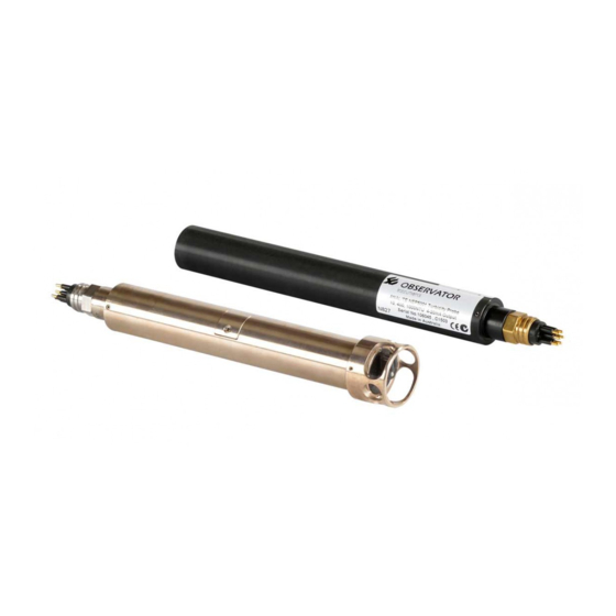
- Page 4 Summary Thanks for purchasing the new NEP-5000 turbidity probe. It will give you years of service if you install and maintain the probe according to the guidelines set out in this manual. Our successful NEP-5000 family of Analite turbidity sensors offers enhanced performances in a small and revolutionary design with greater ease of deployment at lower cost.
-
Page 5: Table Of Contents
Table of contents Applications ........................8 Safety ..........................9 Specification ........................10 What you will find in the box ..................13 Accessories ........................14 How to use this manual (where to begin?) ..............16 Default settings ..........................16 Finding the correct wiring diagram for your sensor ................17 How to configure and calibrate your sensor .................. - Page 6 8.4.1 #WD4-A RS485 glanded ......................58 8.4.2 #WD4-B Analog glanded......................59 8.4.3 #WD4-C voltage glanded ......................60 8.4.4 #WD4-D RS422 glanded......................61 RS485/Pressure SubConn connector option (#WD5) ............... 62 8.5.1 #WD5-A RS485 SubConn ...................... 63 RS485/Pressure glanded-NEP cable option (#WD6) ............... 64 8.6.1 #WD6-A RS485 glanded ......................
- Page 7 EC Declaration of Conformity according to Council Directive 2004/108/EC ..... 104 Manual | NEP-5000 Page 7 | 105 Status: Final | Not confidential V20200311...
-
Page 8: Applications
(deployment times) required. Although advanced digital processing in the Analite NEP-5000 will effectively measure the true turbidity of water when large particles are passing by the optical face, it is recommended to take steps to protect the optical face from possible abrasive effects these particles may cause. -
Page 9: Safety
Safety Always refer to the appropriate wiring diagram and apply appropriate power levels to the sensor to avoid potential destruction of the sensor that may also harm you. Do not connect anything potentially electrical to the metal body of the sensor as it may result in electrical shocks that could harm you or destroy your instruments. -
Page 10: Specification
Specification Glanded sensor dimensions Length 321.37mm Diameter 31.70mm SubConn sensor dimensions Length 274.5mm Diameter 31.7mm Manual | NEP-5000 Page 10 | 105 Status: Final | Not confidential V20200311... - Page 11 Mechanical Weight NEP-5000 Delrin models 300 grams – probe only*. NEP-5000 metal models 770 grams – probe only*. *100gms connector plus 70 grams per meter of cable. Case construction Delrin composite casing is standard. 316 stainless steel Titanium Anti-biofouling CW352H 70/30% Copper/Nickel. Cable Glanded-NEP cable specification: 7 cores + shield, 6mm nominal dia.
- Page 12 Specification Accuracy including linearity & ±1% at 25°C, up to 5,000NTU temperature drift Zero drift Less than ±0.2NTU Calibration Factory calibrated using non-toxic AEPA polymer solutions. Power 8-30V Direct Current (DC) • 15mA on • 25mA reading • 60mA wiping Settling time/measurement Single range (2-4s), auto-range (4-6s) acquisition time...
-
Page 13: What You Will Find In The Box
What you will find in the box When the product is delivered, this is what you will find in the box: Items found in the box NEP-5000 Probe NEP-5000 NEP-CBL - Probe cable in meters. Blue box calibration module and Universal Serial Bus (USB) cable* Module and PC configuration and calibration software. -
Page 14: Accessories
Accessories Observator Instruments offers a wide range of accessories for the NEP-5000 range of products directly available from the website: Accessories Case NEP-CASE Wiper replacement kit NEP-WIPER-KIT - comprising of 4 silicon wipers and a hex fastening key. Shroud NEP-SHRD-D - Delrin protective shroud... - Page 15 Accessories Calibration kit for SubConn probes** NEP-CFG-SF - comprising of a blue box calibration module, USB cable and a SubConn female pigtail. (**) Only for NEP-5000 with male SubConn connector. Wiring is different for SDI-12 and RS422/RS485. Calibration solutions NEP-CAL-GSF Brown bottle for calibration NEP-CAL-BTL NEP-5000 connection cable...
-
Page 16: How To Use This Manual (Where To Begin?)
How to use this manual (where to begin?) All NEP-5000 sensors come with default factory settings which are unique to each sensor variation of the NEP-5000. Users may also request desired settings at the time when placing the order. 6.1 Default settings The default settings for each NEP-5000 glanded &... -
Page 17: Finding The Correct Wiring Diagram For Your Sensor
Using this configuration, the user only requires to connect 3 wires during the time of the calibration process. To facilitate trouble free communication with the PC, Observator Instruments provides a module called “calibration module” that converts one wire calibration data to USB and generates 12V DC from available USB 5V. -
Page 18: Subconn Options Only
2. Connect the NEP-CBL-CON to the blue box calibration module (refer to section 6.5: “Connect the calibration module”). Figure 6.C: Example of configuration for SubConn SDI-12 probes Note: Always be mindful of following the correct pinout which changes based on your probe configuration. -
Page 19: Glanded-Nep Options Only
2. Connect the SubConn female pigtail to the blue box calibration module (refer to section 6.5: “Connect the calibration module”). Figure 6.E: Example of configuration for SubConn SDI-12 probes Note: Always be mindful of following the correct pinout which changes based on your probe configuration. -
Page 20: Connect The Calibration Module
6.5 Connect the calibration module NEP-5000 probes are calibrated using the “Blue box calibration module” (see Figure 6.G). 1. Connect your sensor(s) to the calibration module according to the “Pinout & wiring diagram” table on chapter 8. Calibration module pin Refer to Sensor wire to connect number... -
Page 21: Nep-5000 Capabilities
NEP-5000 capabilities This section will describe all the capabilities of the NEP-5000 sensor and its features available for measuring, communicating, optical cleaning and secondary sensor options. • In measurement settings, the user may change slew-rate, the behavior of auto-range, and statistical package according to the application requirements. -
Page 22: Single-Range Measurement
7.1.1 Single-range measurement When the NEP-5000 is configured as a single-range, the sensor will apply the correct slew-rate during its measurement period. The new-measurement is added to the statistical data-stack for future calculations and passes to the output stage. Advantages of single-range measurements: Single-range measurement is ideal for applications that require fast response when constant monitoring is required. -
Page 23: Features In Communication
7.2 Features in communication The NEP-5000 consists of a wide variety of communication related features such as: • Periodic data free-flow. • Data-request mode (polled-mode). • SDI-12 mode. • Measurement via Analog interface. 7.2.1 Periodic data free-flow The NEP-5000 in data free-flow mode provides periodic data in single-range or auto-range measurements while supporting periodic optical wipe options. - Page 24 Statistical via free-flow mode: To obtain a statistical measurement via free-flow mode, the user needs to select the appropriate statistical settings using the PC configuration software. When selected, the data will be out putted according to the selected free-flow period. Note: If selected statistical data takes say 40s, the user must wait 40s from start up to receive the first accurate result.
-
Page 25: Data-Request Mode (Polled-Mode)
7.2.2 Data-request mode (polled-mode) The NEP-5000 in data polled-mode provides data on request in single-range or auto-range measurements. Temperature measurement is also available as a secondary parameter. Functions that can be controlled via polled-mode: • Optical wiper. • Turbidity measurement ranges. •... - Page 26 3. Available polled-mode output sentence types are: • Sensor ID, turbidity, temperature. • Sensor ID, turbidity. • Sensor ID, median, average, minimum, maximum. Figure 7.E: Poll-mode output settings Obtain a measurement: To obtain a measurement via polled-mode, the logger needs to send “Sensor ID” and “read” followed by carriage return [0x0D].
- Page 27 Perform a wipe: To carry out an optical wipe via polled-mode, the logger needs to send “Sensor ID” and “wipe” followed by carriage return [0x0D]. Please refer to the command below: sensor_id, wipe[enter(enter(hex’D’)] Note: The desired wiper response can be set using the PC configuration software, please refer to section 7.3: “Optical wiper: Features and configurations”.
- Page 28 Figure 7.G: Polled mode address Statistical measurement via polled-mode as legacy NEP-395: This command may output a series of single reading turbidity measurements and then automatically calculate its statistical output. This is identical to the NEP-395. Please refer to the command below: sensor_id, mesu[enter(hex’D’)] Manual | NEP-5000 Page 28 | 105...
-
Page 29: Mode
7.2.3 SDI-12 mode The NEP-5000 in SDI-12 protocol provides a wide variety of parameters and features such as single or auto-range turbidity measurements, optical wipe, range select and statistical measurement. SDI-12 configuration of the NEP-5000 software provides a variety of selections customized to your application. - Page 30 SDI-12 acknowledgement command returns the sensor address on request: ****Address query command (?!)**** Return a<CR><LF> Eg- ?!2<CR><LF> Note: The sensor must not be in a multiple sensor SDI-12 bus when invoked. Sensor specific command set • Single measurement of turbidity: Using single measurement command (aM!) the user may select single range measurement or auto- range measurement.
- Page 31 To read a statistical measurement (aD1!). Note: 6 parameters include with single measurement of turbidity (aD0!) followed by (aD1!). **** Full statistical measurement read**** Send data command (aD1!) Return a+TT.TT+MMMM.MM+AAAA.AA+LLLL.LL+SSSS.SS<CR><LF> Eg- 1+23.58+714.53+714.52+714.24+714.85<CR><LF> Note that. TT.TT= Temperature MMMM.MM = Median AAAA.AA=Average LLLL.LL = Minimum value SSSS.SS = Maximum Value •...
-
Page 32: Measurement Via Analog Interface
7.2.4 Measurement via Analog interface Common features for Analog current and voltage configuration This section explains how to enable and do scaling of the Analog output for both voltage driver option and current driver option. The NEP-5000 Analog output option can provide a wide variety of different Analog outputs and ranges. Please refer to the calibration of the Analog output section for further information. - Page 33 Figure 7.J: Current driver calibration wiring The following steps detail the calibration component of the output driver that is used to set up the desired limits of the current (e.g. 4-20mA or 0-20mA). 1. Select the option “Set 0NTU Offset” (Figure 7.K: #1). 2.
- Page 34 Calibration of voltage output This section shows how to set up for the calibration of the voltage output and is a step-by-step instruction procedure for its calibration. Please wire up your NEP-5000 voltage output option according to the schematic (Figure 7.N). Use the appropriate wiring colour based on your probe model (see chapter 8: “Pinout &...
-
Page 35: Optical Wiper: Features And Configurations
7.3 Optical wiper: Features and configurations The NEP-5000 optical wiping system offers a comprehensive list of wiping solutions to meet the needs of unique applications. Some of the available features are: • Single direction. • Return wipe. • Scrub wipe. •... -
Page 36: Recommended Method Of Triggering The Optical Wiper Using A Dedicated Wiper Wire
2. Wiper timeout (Figure 7.R: #2) This timeout value allows the user to specify the amount of time that the wiper is activated during a wiper jam. Note: Timeout value affects differently to each wiper mode. 3. Wipe on powerup (Figure 7.R: #3) This option allows the user to turn on the optical wiper automatically during the sensor power up. -
Page 37: Available Optical Wiping Options For Output Configurations
7.3.3 Available optical wiping options for output configurations Wiping options are unique to each output as described below: 1. Available optical wiping options for “Periodic data free-flow” mode: • Periodic optical wiper activation. • Power on optical wiper activation. 2. Available optical wiping options for “Data-request mode (polled-mode)” mode: •... -
Page 38: Pinout & Wiring Diagram
Pinout & wiring diagram • SubConn with NEP-CBL-CON option. 7 core NEP cable NEP-CBL-CON: SubConn to NEP cable convertor cable NEP-5000 SubConn sensor Shield (lug) – connect to GND RS232/Analog SubConn RS485/RS422/Analog SubConn RS485/Pressure SubConn connector option (#WD1) connector option (#WD3) connector option (#WD5) SubConn male connector 7 core NEP cable colours... - Page 39 7 core NEP cable NEP-CBL-CON: SubConn to NEP cable convertor cable NEP-5000 SubConn sensor Shield (lug) – connect to GND SDI-12/Analog SubConn connector option (#WD7) SubConn male connector 7 core NEP cable colours (sensor end) Pin 1 Power GND, SDI12 GND, and Green voltage output GND Pin 2...
- Page 40 • SubConn option. SubConn female connector SubConn cable (black rubber) NEP-5000 SubConn sensor RS232/Analog SubConn connector RS485/RS422/Analog SubConn RS485/Pressure SubConn connector SDI-12/Analog SubConn connector SubConn male option (#WD1) connector option (#WD3) option (#WD5) option (#WD7) 6 core SubConn cable colours connector (sensor end) Pin 1 Power GND, SDI12 GND, and voltage...
- Page 41 • Glanded-NEP cable option. 7 core NEP cable (PUR) NEP-5000 Glanded sensor Shield (lug) – connect to GND RS232/Analog glanded-NEP cable option RS485/RS422/Analog glanded-NEP cable RS485/Pressure glanded-NEP cable option SDI-12/Analog glanded-NEP cable option (#WD2) option (#WD4) (#WD6) (#WD8) 7 core NEP cable colours Power +10V to +24V DC Brown Power +10V to +24V DC...
-
Page 42: Rs232/Analog Subconn Connector Option (#Wd1)
8.1 RS232/Analog SubConn connector option (#WD1) Calibration wiring setup for RS232 Analog SubConn: Windows 7 or newer 1280 x 720 or better .Net 4.0 runtime Original Equipment Manufacturer (OEM) calibration software DC in 12V DC power supply (power pack) Power (SubConn #1, Black) GND (SubConn #2, White) Detail #WD1 scale 2:1... -
Page 43: Wd1-A Rs232 Subconn
8.1.1 #WD1-A RS232 SubConn Connect NEP-5000 to RS232 logger: # WD1-A: RS232 (SubConn) Figure 8.B: RS232 SubConn logger configuration Description The NEP-5000 sensor, with RS232 communication option, provides a comprehensive list of functionalities such as: • Data-streaming (RS232 free-flow) in a variety of desired periods while providing various wiping options. - Page 44 RS232 polled-mode selection Figure 8.D: RS232 polled-mode selection When RS232 selection being used with polled-mode, the user must select (Figure 8.D: #2) as “Polled Digital”, then select (Figure 8.D: #3) COM type as “RS232”. Then press, selection (Figure 8.D: #4) and (Figure 8.D: #5) to save settings permanently to the sensor memory.
-
Page 45: Wd1-B Analog Subconn
8.1.2 #WD1-B Analog SubConn # WD1-B: 4-20mA (SubConn) Figure 8.E: Analog SubConn logger configuration Note: Activate wiper: Short pin 5 to GND. Further information, refer to section 7.3.2: “Recommended method of triggering the optical wiper using a dedicated wiper wire”. Description The NEP-5000 has current driver option outputs with turbidity is represented as: 4-20mA or 0-20mA. -
Page 46: Wd1-C Voltage Subconn
8.1.3 #WD1-C Voltage SubConn Connect NEP-5000 voltage logger: # WD1-C: Voltage (SubConn) Figure 8.G: Voltage SubConn logger configuration Note: To activate wiper, short pin 5 to GND (further information, refer to section 7.3.2: “Recommended method of triggering the optical wiper using a dedicated wiper wire”). Description The NEP-5000 has voltage driver option outputs turbidity is represented as: -2.5V to +2.5V, 0 to 2.5V or 0 to 1V. -
Page 47: Rs232/Analog Glanded-Nep Cable Option (#Wd2)
8.2 RS232/Analog glanded-NEP cable option (#WD2) Calibration wiring setup for RS232 Analog glanded: Windows 7 or newer 1280 x 720 or better .Net 4.0 runtime OEM calibration software DC in 12V DC power supply (power pack) Power (#1, Brown) GND (#2, Green) Detail #WD2 SCALE 2:1 Calibration (#6, Grey) -
Page 48: Wd2-A Rs232 Glanded
8.2.1 #WD2-A RS232 glanded Connect the NEP-5000 to the RS232 logger: # WD2-A: RS232 (glanded) Figure 8.J: RS232 glanded logger configuration Description The NEP-5000 sensor with RS232 communication option provides a comprehensive list of functionalities such as: • Data-streaming (RS232 free-flow) in a variety of desired periods while providing various wiping options. - Page 49 RS232 polled-mode selection Figure 8.L: RS232 polled-mode selection When the RS232 selection is being used with polled-mode, the user must select (Figure 8.L: #2) as “Polled Digital”, then select (Figure 8.L: #3) COM type as “RS232”. Then press, (Figure 8.L: #4) and (Figure 8.L: #5) to save settings permanently to the sensor memory.
-
Page 50: Wd2-B Analog Glanded
8.2.2 #WD2-B Analog glanded Connect the NEP-5000 to the 4-20mA logger: # WD2-B: 4-20mA (glanded) Figure 8.M: Analog glanded logger configuration Note: Activate wiper: Short grey wire to GND. Further information, refer to section 7.3.2: “Recommended method of triggering the optical wiper using a dedicated wiper wire”. Description The NEP-5000 with the current driver option outputs turbidity is represented as: 4-20mA or 0-20mA. -
Page 51: Wd2-C Voltage Glanded
8.2.3 #WD2-C Voltage glanded # WD2-C: Voltage (glanded) Figure 8.O: Voltage glanded logger configuration Note: Activate wiper: short grey wire to GND. Further information, refer to section 7.3.2: “Recommended method of triggering the optical wiper using a dedicated wiper wire”. Description The NEP-5000 with voltage driver option outputs turbidity is represented as: -2.5V to +2.5V, 0 to 2.5V or 0 to 1V. -
Page 52: Rs485/Rs422/Analog Subconn Connector Option (#Wd3)
8.3 RS485/RS422/Analog SubConn connector option (#WD3) Calibration wiring setup for RS485/RS422 Analog SubConn: Windows 7 or newer 1280 x 720 or better .Net 4.0 runtime OEM calibration software DC in 12VDC power supply (power pack) Power (Subconn #1, Black) GND (Subconn #2, White) Detail #WD3 Calibration (Subconn #5, Orange) SCALE 2:1... -
Page 53: Wd3-A Rs485 Subconn
8.3.1 #WD3-A RS485 SubConn Connect the NEP-5000 to the RS485 logger: # WD3-A: RS485 (SubConn) Figure 8.R: RS485 SubConn logger configuration Description The NEP-5000 sensor with RS485 communication option provides on-request measurement and control over the sensor. This option also allows to control multiple sensors using the same RS485 bus (e.g. extra turbidity sensors in various heights). -
Page 54: Wd3-B Analog Subconn
8.3.2 #WD3-B Analog SubConn Connect NEP-5000 to the 4-20mA logger: # WD3-B: 4-20mA (SubConn) Figure 8.T: Analog SubConn logger configuration Note: Activate wiper: Short pin 5 to GND. Further information, refer to section 7.3.2: “Recommended method of triggering the optical wiper using a dedicated wiper wire”. Description The NEP-5000 with current driver option outputs turbidity is represented as: 4-20mA or 0-20mA. -
Page 55: Wd3-C Voltage Subconn
8.3.3 #WD3-C Voltage SubConn Connect NEP-5000 voltage logger: # WD3-C: Voltage (SubConn) Figure 8.V: Voltage SubConn logger configuration Note: Activate wiper: Short pin 5 to GND. Further information, refer to section 7.3.2: “Recommended method of triggering the optical wiper using a dedicated wiper wire”. Description The NEP-5000 with voltage driver option outputs turbidity is represented as: -2.5V to +2.5V, 0 to 2.5V or 0 to 1V. -
Page 56: Wd3-D Rs422 Subconn
8.3.4 #WD3-D RS422 SubConn Connect NEP-5000 to RS422 logger: # WD3-D: RS422 free-flow (SubConn) Figure 8.X: RS422 SubConn logger configuration Description The NEP-5000 sensor with RS422 communication option provides streaming data over RS422 communication bus. This option allows a variety of desired data output periods while providing various wiping options. -
Page 57: Rs485/Rs422/Analog Glanded-Nep Cable Option (#Wd4)
8.4 RS485/RS422/Analog glanded-NEP cable option (#WD4) Calibration wiring setup for RS485/RS422 Analog glanded: Windows 7 or newer 1280 x 720 or better .Net 4.0 runtime OEM calibration software DC in 12VDC power supply (power pack) Power (#1, Brown) GND (#2, Green) Detail #WD4 SCALE 2:1 Calibration (#6, Grey) -
Page 58: Wd4-A Rs485 Glanded
8.4.1 #WD4-A RS485 glanded Connect NEP-5000 to the RS485 logger: # WD4-A: RS485 (glanded) Figure 8.AA: RS485 glanded logger configuration Description The NEP-5000 sensor with RS485 communication option provides on-request measurement and control over the sensor. This option also allows to control multiple sensors using the same RS485 bus (e.g. extra turbidity sensors in various heights). -
Page 59: Wd4-B Analog Glanded
8.4.2 #WD4-B Analog glanded Connect NEP-5000 to the 4-20mA logger: # WD4-B: 4-20mA (glanded) Figure 8.CC: Analog glanded logger configuration Note: Activate wiper: Short grey wire to GND. Further information, refer to section 7.3.2: “Recommended method of triggering the optical wiper using a dedicated wiper wire”. Description The NEP-5000 with current driver option outputs turbidity is represented as: 4-20mA or 0-20mA. -
Page 60: Wd4-C Voltage Glanded
8.4.3 #WD4-C voltage glanded Connect NEP-5000 voltage logger: # WD4-C: Voltage (glanded) Figure 8.EE: Voltage glanded logger configuration Note: Activate wiper: Short grey wire to GND. Further information, refer to section 7.3.2: “Recommended method of triggering the optical wiper using a dedicated wiper wire”. Description The NEP-5000 with voltage driver option outputs turbidity is represented as: -2.5V to +2.5V, 0 to 2.5V or 0 to 1V. -
Page 61: Wd4-D Rs422 Glanded
8.4.4 #WD4-D RS422 glanded Connect the NEP-5000 to the RS422 logger: # WD4-D: RS422 (glanded) Figure 8.GG: RS422 glanded logger configuration Description The NEP-5000 sensor with the RS422 communication option provides streaming data over the RS422 communication bus. This option allows a variety of desired data output periods while providing various wiping options. -
Page 62: Rs485/Pressure Subconn Connector Option (#Wd5)
8.5 RS485/Pressure SubConn connector option (#WD5) Calibration wiring setup for the RS485 Pressure SubConn: Windows 7 or newer 1280 x 720 or better .Net 4.0 runtime OEM calibration software DC in 12VDC power supply (power pack) Power (SubConn #1, GND (SubConn #2, White) Detail #WD5 SCALE 2:1 Turbidity calibration... -
Page 63: Wd5-A Rs485 Subconn
8.5.1 #WD5-A RS485 SubConn Connect the NEP-5000 to the RS485 logger: # WD5-A: RS485 mult-drop (SubConn) Figure 8.JJ: RS485 SubConn logger configuration Description The NEP-5000 sensor with the RS485 communication option provides on-request measurement and control over the built-in multiple sensors. This option also allows to control multiple sensors using the same RS485 bus (e.g. -
Page 64: Rs485/Pressure Glanded-Nep Cable Option (#Wd6)
8.6 RS485/Pressure glanded-NEP cable option (#WD6) Calibration wiring setup for RS485 pressure glanded: Windows 7 or newer 1280 x 720 or better Net 4.0 runtime calibration software DC in 12VDC power supply (power pack) Power (#1, Brown) GND (#2, Green) Detail #WD6 Pressure Calibration (#5, Yellow) SCALE 2:1... -
Page 65: Wd6-A Rs485 Glanded
8.6.1 #WD6-A RS485 glanded Connect the NEP-5000 to the RS485 logger: # WD6-A: RS485 mult-drop (glanded) Figure 8.MM: RS485 glanded logger configuration Description The NEP-5000 sensor with RS485 communication option provides on-request measurement and control over the built-in multiple sensors. This option also allows to control multiple sensors using the same RS485 bus (e.g. -
Page 66: Sdi-12/Analog Subconn Connector Option (#Wd7)
8.7 SDI-12/Analog SubConn connector option (#WD7) Calibration wiring setup for SDI-12 Analog SubConn: Windows 7 or newer 1280 x 720 or better .Net 4.0 runtime OEM calibration software DC in 12VDC power supply (power pack) Power (SubConn #3, Red) GND (SubConn #1, Black) Detail #WD7 SCALE 2:1 Calibration (SubConn #6, Blue) -
Page 67: Wd7-A Sdi-12 Subconn
8.7.1 #WD7-A SDI-12 SubConn Connect the NEP-5000 to the SDI-12 logger: # WD7-A: SDI-12 (SubConn) Figure 8.PP: SDI-12 SubConn logger configuration Description When the NEP-5000 sensor is configured as SDI-12 communication, it can offer a full range of sensor operations via the SDI-12 bus. Some of these options are initiating and reading turbidity measurements, statistical measurements, changing measurement ranges and operating the optical wiper. -
Page 68: Wd7-B Analog Subconn
8.7.2 #WD7-B Analog SubConn Connect the NEP-5000 to the 4-20mA logger: # WD7-B: 4-20mA (SubConn) Figure 8.RR: Analog SubConn logger configuration Note: Activate wiper: Short pin 6 to GND. Further information, refer to section 7.3.2: “Recommended method of triggering the optical wiper using a dedicated wiper wire”. Description The NEP-5000 with current driver option outputs turbidity is represented as: 4-20mA or 0-20mA. -
Page 69: Wd7-C Voltage Subconn
8.7.3 #WD7-C voltage SubConn Connect NEP-5000 voltage logger: # WD7-C: Voltage (SubConn) Figure 8.TT: Voltage SubConn logger configuration Note: Activate wiper: Short pin 6 to GND. Further information, refer to section 7.3.2: “Recommended method of triggering the optical wiper using a dedicated wiper wire”. Description The NEP-5000 with voltage driver option outputs turbidity is represented as: -2.5V to +2.5V, 0 to 2.5V or 0 to 1V. -
Page 70: Sdi-12/Analog Glanded-Nep Cable Option (#Wd8)
8.8 SDI-12/Analog glanded-NEP cable option (#WD8) Windows 7 or newer Calibration wiring setup for SDI-12 Analog glanded: 1280 x 720 or better .Net 4.0 runtime OEM calibration software DC in 12VDC power supply (power pack) Power (#1, Brown) GND (#2, Green) Detail #WD8 SCALE 2:1 Calibration (#6, Grey) -
Page 71: Wd8-A Sdi-12 Glanded
8.8.1 #WD8-A SDI-12 glanded # WD8-A: SDI-12 (glanded) Figure 8.WW: SDI-12 glanded logger configuration Description When the NEP-5000 sensor is configured as SDI-12 communication, it can offer a full range of sensor operations via the SDI-12 bus. Some of these options are initiating and reading turbidity measurements, statistical measurements, changing measurement ranges and operating the optical wiper. -
Page 72: Wd8-B Analog Glanded
8.8.2 #WD8-B Analog glanded Connect NEP-5000 to 4-20mA logger: # WD8-B: 4-20mA (glanded) Figure 8.YY: Analog glanded logger configuration Note : Activate wiper: Short grey wire to GND. Further information, refer to section 7.3.2: “Recommended method of triggering the optical wiper using a dedicated wiper wire”. Description The NEP-5000 with current driver option outputs turbidity is represented as: 4-20mA or 0-20mA. -
Page 73: Wd8-C Voltage Glanded
8.8.3 #WD8-C voltage glanded Connect NEP-5000 voltage logger: # WD8-C: Voltage (glanded) Figure 8.AAA: Voltage glanded logger configuration Note : Activate wiper: Short grey wire to GND. Further information, refer to section 7.3.2: “Recommended method of triggering the optical wiper using a dedicated wiper wire”. Description The NEP-5000 with voltage driver option outputs turbidity is represented as: -2.5V to +2.5V, 0 to 2.5V or 0 to 1V. -
Page 74: Connect To The Calibration Software
Connect to the calibration software This section will guide the user with step-by-step instructions on how to connect the NEP-5000 sensor to its calibration PC software. Note: For starting up information, please refer to chapter 6: “How to use this manual (where to begin?)”. - Page 75 The driver is not installed Figure 9.B: Device manager window • Right click and select “Update device software”, then choose “driver software from your computer” option. • Using the “Browse” button select “optic diver” when prompted and “OK”. • Wait for the completion of the driver installation. •...
-
Page 76: Run Nep-Oem Software
9.1.2 Run NEP-OEM software 1. Press “Start” button. Figure 9.C: Start NEP-OEM software 2. Select your communication port from the dropdown menu and press “OK” to continue. Figure 9.D: Selection of the communication port 3. The output window should show the following when the correct communications port is selected: Figure 9.E: Output window overview 4. -
Page 77: Make The Calibration Connection With The Sensor
9.2 Make the calibration connection with the sensor Note: Please refer to section 9.1: “Installing the probe for the first time” for connecting and installing drivers first. 1. Go to “Tools”, “Calibration” and select “OEM Calibration Turbidity”. Figure 9.F: Select OEM Calibration Turbidity option 1. - Page 78 Immediately, after pressing “Connect button”, long press (1 second) and release the “RESET” button on the calibration module (blue box) to power cycle the sensor. Figure 9.H: Calibration module “RESET” Note: If you do not press the “RESET” button in-time, an error message will be shown, the user may restart step (2) of the above procedure.
-
Page 79: Serial Number
Figure 9.J: General settings menu 9.2.1 Serial number A unique serial number is assigned to the running probe during manufacturing. Serial numbers cannot be changed. 9.2.2 Password Factory usage only. 9.2.3 Sensor ID Current ID of the running sensor. Sensor ID can range from 0 to 9. Sensor ID is used for serial output. 9.2.4 Available sensor options Provides a list of available output interfaces, corresponding to the hardware that is physically installed. -
Page 80: Turbidity Calibration
10 Turbidity calibration The NEP-5000 sensor comes with a full factory calibration and this includes profiling of the optics (multi- point calibration) and calibration of all 3 ranges (2-point calibration). When the optical data profile is already available (from the factory calibration file), only a 2-point calibration is generally required at each service interval by the user. -
Page 81: When Do You Need To Calibrate
10.1 When do you need to calibrate? • It is recommended that after one year of field use, the user may verify the calibration using appropriate calibration solutions mentioned in the original factory calibration certificate. The user may order this solution when ordering the sensor. -
Page 82: Before You Begin Calibration
10.3 Before you begin calibration Before you begin, please make sure you have the following items: 1. Prepare AMCO CLEAR® turbidity standard solutions for all three ranges. Low-range Mid-range High-range Low calibration point (bottom) 0NTU turbidity standard High calibration point (top) 10NTU solution 400NTU solution 3,000NTU solution... - Page 83 2. It is recommended to use quality distilled water as dissolved solids – 3 parts per 1,000,000. Please note, accurate bottom end calibration is essential for low range turbidity measurements. 3. It is recommended to use Ultraviolet (UV) absorbent bottles. The UV absorbent bottles help to minimize the light bouncing effect caused by the container’s wall.
-
Page 84: 2-Point Calibration For 3 Ranges
10.4 2-point calibration for 3 ranges Note: To obtain the NEP-5000 data sheet specification, the following procedures must be followed. 10.4.1 Clean the sensor Begin the calibration procedure by cleaning the sensor optical face using a wash solution. Move the probe up and down in the water. -
Page 85: Load The Optical Profile
10.4.4 Load the optical profile Load the optical profile (original factory calibration of the sensor) by downloading appropriate CFG file (match serial number) from the “Analite website” and apply it to the sensor. • Download the CFG file to your local drive. Your sensor serial number, right click to download as a file Figure 10.H: Load the optical profile... - Page 86 • Press “Yes” to write newly imported factory calibration data to the attached sensor. Figure 10.K: Apply calibration data file to the sensor • Please wait until the process is fully completed. It may take up to a minute. Figure 10.L: Applying changes •...
-
Page 87: Set Up Zero-Point Calibration Values For All Ranges
10.4.5 Set up zero-point calibration values for all ranges Note: This stage will be required for every range that the user wishes to calibrate. • After cleaning the sensor by dipping the sensor a few times into the washed solution, dry and then submerge the sensor into the 0NTU solution as shown below: Sensor Liquid level... - Page 88 • Now, select “LOW NTU” and click “Set” and wait until the “LOW NTU” is set (the set button will turn pink). Figure 10.P: Low NTU • Tick “Get live data” tick box to read current measurement from the sensor, the “NTU” & “RAW” should display un-calibrated 0 NTU solution values.
- Page 89 • Now, click “Set” and read the live data by tick “Get live data”, the reading is getting closer to 0NTU solution figure. Figure 10.S: Set the 0NTU Raw value • To make 0 NTU reading better, increase “0NTU (Input RAW)” by “2NTU” (as 180 in the picture), click “Set”...
-
Page 90: Set Up Low-Range Top Calibration Value
10.4.6 Set up low-range top calibration value • Please insert the sensor to the appropriate top limit value solution (e.g. 10NTU). Sensor Liquid level Clearance to the bottom (5cm) Figure 10.U: Insert the sensor in the top calibration value Important note: The distance between the bottom of the container and sensors optical face must be a minimum of 5cm. - Page 91 • Now, select “LOW NTU”, then “Set”, and tick “Get live data” tick box to read current measurement from the sensor. It should display the “RAW” & “NTU” values, but the “NTU” reading is out of the low top-range NTU value (it reads 36.795NTU instead of 10NTU).
- Page 92 • Press: “Set”, and “Get live data”, but the reading is still un-desirable. Redo all previous steps until the reading is close enough to the high top-range NTU value. Figure 10.Z: Set the low-range top calibration value • Press “Save calibration” to commit your new calibration data to the permanent memory inside the sensor.
- Page 93 • Clean the sensor optical face using a wash solution. Move the probe up and down in the water. Make sure you never touch the optics. Then dry the sensor with the air duster or cloth. Figure 10.BB: Wash and dry the sensor Two-point low-range calibration has now been completed.
-
Page 94: Set Up Mid-Range Top Calibration Value
10.4.7 Set up mid-range top calibration value • Please insert the sensor to the appropriate top limit value solution (e.g. 400NTU). Sensor Liquid level Clearance to the bottom (5cm) Figure 10.CC: Insert the sensor in the top calibration value Important note: The distance between the bottom of the container and sensors optical face must be a minimum of 5cm. - Page 95 • Now, select “Medium NTU”, then “Set”, and tick “Get live data” tick box to read the current measurement from the sensor. It should display the “RAW” & “NTU” values, but the “NTU” reading is out of the medium top-range NTU value (it reads 1.97NTU instead of 400NTU).
- Page 96 • Press: “Set”, and “Get live data”, but the reading is still un-desirable, redo all previous steps until the reading is close enough to the high top-range NTU value. Figure 10.HH: Set the mid-range top calibration value • Press “Save calibration” to commit your new calibration data to the permanent memory inside the sensor.
- Page 97 • Clean the sensor optical face using a wash solution. Move the probe up and down in the water. Make sure you never touch the optics. Then dry the sensor with the air duster or cloth. Figure 10.JJ: Wash and dry the sensor Two-point medium-range calibration has now been completed.
-
Page 98: Set Up High-Range Top Calibration Value
10.4.8 Set up high-range top calibration value • Please insert the sensor to the appropriate top limit value solution (e.g. 3,000NTU). Sensor Liquid level Clearance to the bottom (5cm) Figure 10.KK: Insert the sensor in the top calibration value Important note: The distance between the bottom of the container and sensors optical face must be a minimum of 5cm. - Page 99 • Now, select “High NTU”, then “Set”, and tick “Get live data” tick box to read current measurement from the sensor. It should display the “RAW’ & “NTU” values, but the “NTU” reading is out of the high top-range NTU value (it reads 1140.63NTU instead of 3,000NTU).
- Page 100 • Press: “Set”, and “Get live data”, but the reading is still un-desirable, redo all previous steps until the reading is close enough to the high top-range NTU value. Figure 10.PP: Set the high-range top calibration value • Press “Save calibration” to commit your new calibration data to the permanent memory inside the sensor.
- Page 101 • Clean the sensor optical face using a wash solution. Move the probe up and down in the water. Make sure you never touch the optics. Then dry the sensor with the air duster or cloth. Figure 10.RR: Wash and dry the sensor Two-point high-range calibration has now been completed.
-
Page 102: Frequently Asked Questions (Faq) - Do/Don't
1. Calibrate by the user via a 2-point calibration process described in this manual. 2. Send the unit to Observator Instruments Australia for a full service and calibration of the sensor (highly recommended). -
Page 103: 103
Can I buy replacement wipers and mount them myself? Please refer to “Wiper Replacement” Application note document. Where can I find the technical support contact details? Observator Instruments: Tel: +61 3 8706 5000, Fax: +61 3 8706 5049 Email: sales.au@observator.com 11.6 Software... -
Page 104: Electrical Conformity
12 Electrical conformity EC Declaration of Conformity according to Council Directive 2004/108/EC We, Observator Instruments Pty. Ltd., declare under our sole responsibility that the following products: Analite NEP-5000 series turbidity sensors, Analite NEP-9000 series turbidity sensors, Analite OEM turbidity sensors Manufactured by: Observator Instruments Pty. - Page 105 © Copyright – Observator Group Since 1924 Observator has evolved to be a trend-setting developer and supplier in a wide variety of industries. Originating from the Netherlands, Observator has grown into an internationally oriented company with a worldwide distribution network and offices in Australia, Germany, the Netherlands, Singapore and the United Kingdom.
Need help?
Do you have a question about the Analite NEP-5000 and is the answer not in the manual?
Questions and answers