
Subscribe to Our Youtube Channel
Related Manuals for Varex Imaging 144011


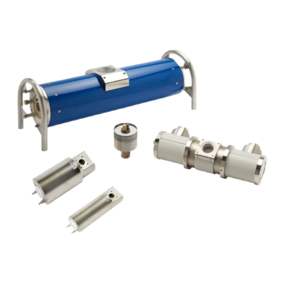
Summary of Contents for Varex Imaging 144011
- Page 1 Spring Loaded R-Type Connectors Installation Before using the X-ray Tube, be sure to read this manual thoroughly along with any other manuals for other system components. Keep this manual where it is easily accessible. ®...
- Page 2 • In no event is Varex Imaging liable for direct, indirect, or consequential injury, damage, or loss of equipment operation time or image data arising from the use of the X-ray Tube, its components, and/or accessories.
- Page 3 Spring Loaded R-Type Connectors For Your Safety To avoid personal injury or product damage, read this manual and all accompanying information carefully before handling, installing, or using the X-ray Tube. Follow all instructions, warnings, and cautions in this manual and all warnings and cautions printed on the warning label.
- Page 4 Warnings and Cautions Spring Loaded R-Type Connectors Warnings and Cautions Installation of the cables must be performed by trained personnel only. WARNING Users, System Installers, and Service Personnel are responsible to WARNING follow all steps outlined for proper installation. Use Varex approved receptacles and silicone grease. WARNING Ensure while handling High Voltage components the following WARNING...
-
Page 5: Table Of Contents
Table of Contents Scope ............. . . 1 Audience. - Page 6 Table of Contents Spring Loaded R-Type Connectors This page intentionally left blank. www.vareximaging.com...
-
Page 7: Scope
Spring Loaded R-Type Connectors Scope This document describes installation for the Spring Loaded R-Type Terminations; CA10SL (R10SL), CA12SL (R24SL), and CA18 (R28SL). Audience This document is for users of the X-ray Tube and for X-ray system manufacturers and X-ray system installers who are responsible for installing the X-ray Tube into an X-ray system. Installation This section describes the installation of the High Voltage components. -
Page 8: Cleaning
Spring Loaded R-Type Connectors Cleaning Obtain the following supplies: • Lint-Free Wipes • Cleaning Tool, see “Section 5.0, Appendix A: Drawings” on page 12 • Isopropyl Alcohol (IPA) • New Powder-Free Gloves Clean the connector and the receptacle before every installation. The use WARNING of a cleaning tool is recommended. - Page 9 Spring Loaded R-Type Connectors Insert cleaning tool into the receptacle, making sure to thoroughly wipe all interior sur- faces. Figure 4 Clean interior surfaces Obtain a new lint-free wipe and apply IPA. Clean the connector before placing into the receptacle. Figure 5 Clean the connector www.vareximaging.com...
-
Page 10: Pre-Gapping
Spring Loaded R-Type Connectors Pre-Gapping Obtain New Powder-Free Gloves. Adjust the cable flange gap according to Table Note Adjust the cable flange with the High Voltage component dry, no grease applied. Table 1 Pre-Gapping Distances CA10/R10 CA12/R24 CA18/R28 5mm - 6mm 6mm - 7mm 6mm - 7mm Insert the cable into the receptacle. -
Page 11: Greasing
Spring Loaded R-Type Connectors Greasing Obtain the following supplies: • Varex Silicone Grease P4 Figure 7 Varex Silicone Grease • New Powder-Free Gloves Remove the connector from the receptacle and Silicone Grease to two sides of the connec- tor according to Table Table 2 Grease Amount... - Page 12 Spring Loaded R-Type Connectors Using new gloves, distribute the grease evenly over the cone surface, until thin layer is visible on entire surface. Do not use dirty gloves to apply grease. Figure 9 Spread grease evenly Too much grease applied can result in a breakdown when system is cold. WARNING Figure 10 Too much grease applied Figure 11 Too much grease applied...
-
Page 13: Installing
Spring Loaded R-Type Connectors Figure 12 Contact tip free of grease Installing Obtain the following supplies: • Screwdriver/key (type will depend on the screws used for the cable flange) • New Powder-Free Gloves Insert the connector carefully into the receptacle without scraping the grease from the cone. - Page 14 Spring Loaded R-Type Connectors Tighten down the cable flange screws, in a criss-cross pattern. Figure 14 Tighten flange screws Verify the correct compression; two parallel rings must be visible through the cable flange window. Figure 15 Parallel rings in flange window If 2 rings are not visible, adjust the gapping distance until 2 rings are WARNING clearly visible.
-
Page 15: Installation Examples
Spring Loaded R-Type Connectors Installation Examples Correct, at room temperature or after cooling down. Two rings visible. Figure 16 Two rings visible, room temperature Correct, during operation. System is hot and the rubber expands, almost three rings visible. Figure 17 Two rings visible, operating temperature www.vareximaging.com... - Page 16 Spring Loaded R-Type Connectors Incorrect, at room temperature. Installed with gap too small or too much grease during installation (which leaked out after tube heated up), only one ring visible. Redo installation. Figure 18 One ring visible, room temperature Incorrect, at room temperature. Installed with gap too big, three rings visible. Can result in a breakdown.
-
Page 17: Maintenance
Spring Loaded R-Type Connectors Incorrect, during operation. System is hot and just two rings visible. Will result in a breakdown when the system is cold or left on long-term standby. Redo installation. Figure 20 Two rings visible, during operation Visually check the presence of the two rings after 48 hours of operation WARNING to make sure the installation was done correctly. -
Page 18: Appendix A: Drawings
Spring Loaded R-Type Connectors Appendix A: Drawings The drawings depicted are of the Cleaning Tool referenced in Section 3.2. The Cleaning Tool may be purchased or a new one designed based on the measurements below. For purchasing information, please contact a sales representative at 49 (0) 315 659 150. Figure 21 Cleaning Tool measurements 1 Figure 22 Cleaning Tool measurements 2 www.vareximaging.com... - Page 19 Spring Loaded R-Type Connectors Figure 23 Cleaning Tool measurements 3 Figure 24 Cleaning Tool measurements 4 www.vareximaging.com...
- Page 20 Spring Loaded R-Type Connectors This page intentionally left blank. www.vareximaging.com...
- Page 21 Spring Loaded R-Type Connectors This page intentionally left blank.
- Page 22 ©2019 Varex Imaging All rights reserved. The Varex Imaging logo and design are registered trademarks of Varex Imaging or its subsidiaries, in the United States and other countries. All other trademarks not owned by Varex Imaging or its subsidiaries that are depicted herein are the property of their respective owners.
Need help?
Do you have a question about the 144011 and is the answer not in the manual?
Questions and answers