
Subscribe to Our Youtube Channel
Related Manuals for Varex Imaging Optica 30 Series


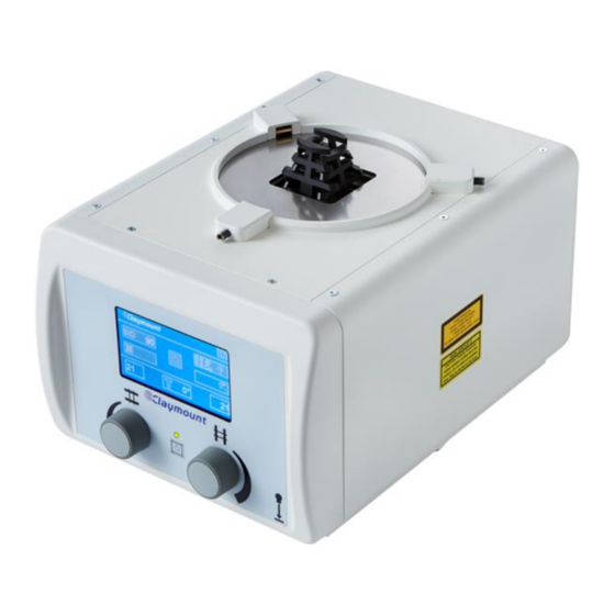
Summary of Contents for Varex Imaging Optica 30 Series
- Page 1 Optica 30 Optica 40 Optica 50 Optica 30/40/50 series 0120 Technical Manual TM50567, Revision: 4.0 www.vareximaging.com...
- Page 2 (This page is intentionally left blank) Technical Manual: TM50567 Optica 30/40/50 series Revision: 4.0 2/56 www.vareximaging.com Date of release: 2019-01-23...
-
Page 3: Table Of Contents
Table of Contents Introduction ............................5 Contact information .........................5 Abbreviations ..........................6 Symbols used in this document ....................7 Advisory...........................7 Radiation danger ........................7 General warnings, cautions and notes ..................8 Labels and markings on the device ..................10 Supplied components ......................12 Device description .......................... 13 Intended use ........................ - Page 4 Although this guide is prepared with utmost care, Varex Imaging Nederland B.V. assumes no responsibility for errors or omissions. Varex Imaging Nederland B.V. cannot be held accountable for damages of any nature arising from the use, and / or use of any options other than original Varex Imaging Nederland B.V. products.
-
Page 5: Introduction
This document is accompanying the Optica 30/40/50 series (see also §1.7). Additional to this Technical Manual a User Manual is supplementary to the INSTRUCTIONS FOR USE. If you need additional information, need support or want to report a problem with the Collimator, please contact your distributor or Varex Imaging Nederland B.V.: Manufacturer Distributor Name Varex Imaging Nederland B.V. -
Page 6: Abbreviations
A communication network that allows remote control of the collimator. Electromagnetic compatibility Electro Static Discharge Medical Equipment Optica 30 X-ray Collimator Optica 30 series Optica 40 X-ray Collimator Optica 40 series Optica 50 X-ray Collimator Optica 50 series Printed Circuit Board. -
Page 7: Symbols Used In This Document
Information regarding accidents that have occurred using the Optica 30/40/50 series must be reported to Varex Imaging Nederland B.V. immediately. Varex Imaging Nederland B.V. is not liable if the provided instructions are not complied with. Varex Imaging Nederland B.V. is not liable if one or more of the following cases apply: •... -
Page 8: General Warnings, Cautions And Notes
Any change or modification carried out by unauthorized personnel may introduce serious hazards. When changes or modification are carried out by unauthorized personnel, Varex Imaging Nederland B.V. cannot be held responsible for injuries or damage to equipment. WARNING: Disconnect power supply before opening collimator. - Page 9 Always keep this manual and read it before using the collimator. NOTE: Please contact your distributor or Varex Imaging Nederland B.V. when the product label or other markings on the outside of the collimator are missing. Requirements for SERVICE PERSONNEL The device may only be installed, repaired or serviced by qualified SERVICE PERSONNEL, i.e.:...
-
Page 10: Labels And Markings On The Device
Labels and markings on the device Symbol Explanation Manufacturer Date of manufacture Serial number Catalogue number. CE-mark directive 93/42/EC; conformity assessment by notified body 0120 0120 (optional feature) SGS recognized component for US & Canada, registration number 710383 (optional feature) 710383 Identification of compliance with FCC 47 CFR Part 15 (optional feature) CAUTION: Federal law restricts this device to sale by or on the order of a... - Page 11 Symbol Explanation Indication cross shutters Indication long shutters Operate field light indicator (Optica 30/40 series only) Manual Control. Automatic Control. Additional filtering. Bucky laser ON indicator Symbol to indicate the selected image field size. Tilting angle. Setup collimator. << Return to previous screen. Accept numeric keyboard value.
-
Page 12: Supplied Components
Otherwise, you should immediately contact your distributor or Varex Imaging Nederland B.V.. It is highly recommended to always use the original packaging during transport and for return shipments. See §9 for storage conditions if the device is not used directly. -
Page 13: Device Description
2. Device description Intended use The device is intended to be used in medical diagnostic applications with restrictions to human diagnostics. The device is intended to be used as accessory of an X-ray system in a professional healthcare facility environment. The device is intended to restrict the dimensions of a diagnostic X-ray field by limiting the primary X-ray beam. -
Page 14: Principle Of Operation
Principle of operation The collimator field dimension is established by 4 pairs of lead covered shutters that can be positioned through the control knobs on the front of the collimator (30/40 Series only). The following symbols are used to indicate each shutter pair: Symbol Definition Description... - Page 15 Bucky laser shutter to close the laser aperture Accessory rails, for a maximum of 2 accessories with a width of 177 mm Accessory lock, for locking the accessory Prior to inserting accessories in the accessory rails check the fit and locking. Hazard of falling accessory.
-
Page 16: Main Dimensions
Main dimensions NOTE: The top shutter dimensions are applicable for fully opened shutters. Collimator Optica 40 Collimator Optica 30/50 The Optica 30 and 50 models have the same dimensions as the Optica 40. This Optica 30 model is delivered without a display. This Optica 50 model is delivered without a display, control knobs, LED button and status LED. -
Page 17: Aluminum Equivalent
Aluminum equivalent The Aluminum equivalent (or ATTENUATION EQUIVALENT) can be found on the product label. The location of the product label can be found in §9.2. The ATTENUATION EQUIVALENT is expressed in [mm] aluminum. Restrictions on use RF communication devices should be kept at a minimum distance of 30 cm. Otherwise the performance of the device can be negatively influenced. -
Page 18: Installation
3. Installation Requirements for service personnel The Collimator may be installed, repaired and / or serviced by qualified personnel only. Installation requirements The Collimator can be installed using regular tooling. Installation instructions WARNING: The collimator contains sensitive electronics. Take measures to prevent ESD. Before the collimator can be used, it needs to be properly installed. -
Page 19: Installation Of Cables
Figure 1 Rear cover screws Installation of cables Cables for power supply and CAN bus must be connected to the green CAN bus connector that is pre- assembled inside the collimator (see §1.8). The connector can be reached when the rear cover of the collimator is removed (see §3.5 for instructions). - Page 20 Figure 2 Collimator power supply cable and CAN cable installation Steps to install the power supply cable and (if needed) the CAN bus interface cable, see Figure 2 for part explanation. Remove the rear cover according instructions in §3.5. Remove the green CAN bus connector Feed the cable through the rear cover.
-
Page 21: Mounting A Dap Meter
Pin assignment for the green CAN bus connector Figure 3 Green CAN bus connector Pin assignment table number: Pin label: Interface: CAN bus Power supply Description CAN - CAN-Low CAN-High 24 V DC 24 V DC 0 V DC 0 V DC 0 V DC Common (CAN-) -
Page 22: Mounting The Collimator To The X-Ray Tube
Figure 4 DAP meter installation Mounting the collimator to the X-ray tube WARNING: Carefully follow the collimator mounting instructions and make sure that the collimator is correctly mounted. Incorrect mounting may lead to dangerous situations such as falling or malfunctioning of the collimator. It is advised to mount the collimator with the X-ray tube exit window facing upwards. - Page 23 The mounting flange and lead insert are mounted on the X-ray tube by 4 countersunk screws. The collimator is mounted to the mounting flange by 3 fixing wedges, see Figure 5 Figure 5 Mounting the Collimator to the X-ray tube Mounting spacers Apply mounting spacers to adjust the distance from the collimator mounting plane and the X-ray tube focal point.
- Page 24 Figure 6 Distance from X-ray tube focal point to collimator mounting plane Mounting of the mounting flange and spacers 1. Place the mounting spacers (when required) on the tube 2. Place the mounting flange and lead insert on top 3. Fix all with the countersunk screws to the X-ray tube. Ensure that sufficient thread is used and the screws fix the flange properly to the X-ray tube mounting surface.
-
Page 25: Calibration And Collimator Setup
Figure 7 Flange lock Calibration and collimator setup This section is only applicable for Optica 40. For Calibration and Setup of the Optica 30 and 50, see CAN bus Service Protocol Messages, §7.3. Access to Service screens for calibration and parameter setup The collimator has 3 Service screens for calibration, parameter setup and embedded software revisions. - Page 26 Service screen 1 Calibration of cross shutters Calibration of the cross shutters is done on the Cross Shutters Calibration Screen. Warning: Not completing all indicated calibration steps will leave the collimator un- calibrated. Warning: Loss of electrical power will leave the collimator un-calibrated. Steps to calibrate cross shutters: 1.
- Page 27 Calibration of long shutters Calibration of the long shutters is done on the Long Shutters Calibration Screen. Warning: Not completing all indicated calibration steps will leave the collimator un- calibrated. Warning: Loss of electrical power will leave the collimator un-calibrated. Steps to calibrate long shutters: 1.
- Page 28 Calibration of rotation sensor Calibration of the rotation sensor is done on the Rotation Sensor Calibration Screen. Warning: Do not select +90° (vertical calibration) and 0° (horizontal calibration) sequentially without rotating the collimator to the corresponding position. This results in unreliable values on the touch screen. Warning: Not completing all indicated calibration steps will leave the collimator un- calibrated.
- Page 29 Calibration of the touch screen During manufacturing, the touch screen is calibrated to be used as expected. When there is a need to re-calibrate the touch screen (e.g. when not responding as expected), follow the next steps to re- calibrate the touch screen (note: this is not part of the Service screen 1): 1.
-
Page 30: Optica
A supported CAN protocol can be made active by entering the applicable protocol ID in the CAN Protocol number field. For further information about the Varex Imaging Nederland B.V. Protocol (Protocol ID: 0), see §7.4. For other CAN protocols, consult your distributor or Varex Imaging Nederland B.V.. -
Page 31: X-Ray Beam Alignment
Service screen 3 Show Logo With this setting, the logo on the Main screen can be made invisible(Off) or visible(On). The default setting is: On Show Inclino With this setting, the Inclino box on the Main screen can be made invisible(Off) or visible(On). The default setting is: On Software revisions are shown in the lower left corner: Main: contains the version for the main board. -
Page 32: Collimator Adjustments
Collimator Adjustments Accuracy of the Light field indication to X-ray field The Collimator X-ray field and the light field are factory calibrated. Ensure the calibration meets local legislation. Calibration setting: The total discrepancies between the edges of the X-ray field and the corresponding edges of the Light Field do not exceed 2% of the distance of the measured plane of the Light Field from the Focal Spot. -
Page 33: Electrical Specification
The collimator has no replaceable fuses. In case of a suspected broken fuse and a power cycle does not result in a functional collimator, the main board is broken, and the collimator needs to be returned to Varex Imaging Nederland B.V. for repair. -
Page 34: Emc Compatibility
EMC compatibility The device conforms to IEC 60601-1-2:2014 for EMC compatibility and must be installed and put into service according to the EMC information provided in this manual. WARNING: Portable RF communications equipment (including peripherals such as antenna cables and external antennas) should be used no closer than 30 cm (12 inches) to any part of the Optica 30/40/50 series, including cables specified by the manufacturer. -
Page 35: Emissions Compliance
4.6.4. Emissions Compliance Guidance and manufacturer’s declaration – electromagnetic emissions The Optica 30/40/50 is intended for use in the electromagnetic environment specified below. The customer or user of the Optica 30/40/50 should assure that it is used in such an environment. Emissions test Compliance Electromagnetic environment - guidance... -
Page 36: Optica 30/40/50 Series
Guidance and manufacturer’s declaration – electromagnetic immunity – Compliance Test Levels for ENCLOSURE PORT IMMUNITY to RF wireless communications equipment Test Maximum MMUNITY Band Service Modulation Distance frequency power TEST LEVEL (MHz) (MHz) (V/m) Bluetooth; WLAN Pulse Modulation 2 450 2 400 –... - Page 37 Guidance and manufacturer’s declaration – electromagnetic immunity – Power and Signal PORTs The Optica 30/40/50 series is intended for use in the electromagnetic environment specified below. The customer or user of the Optica 30/40/50 series should assure that it is used in such an environment. Immunity test Compliance Test level Electromagnetic environment - guidance...
-
Page 38: Operating Instructions
5. Operating instructions Powering ON and OFF POWER ON: When the power supply to the collimator is switched ON, the collimator performs a power-ON self-test for important functions of the collimator. During the power-ON self-test (which takes a few seconds), the status LED is flashing green and a Start-Up Screen is displayed on the touch screen: The result of the power-ON self-test can be: Successful:... -
Page 39: Optica 30/40/50 Series
(Figure only applicable for Optica 40) NOTE: only the first detected fault condition is displayed on the touch screen. (not applicable for Optica 30) NOTE: It is important to send the following information to Varex Imaging Nederland B.V. for analysis: •... -
Page 40: Status Led Color
Status LED color The status LED (30/40 Series only) indicates the Collimator modes. The table below explains the status LED indications. During the POWER-ON self-test and normal OPERATING MODE, the collimator software can detect fault conditions. For troubleshooting see §7.1. Collimator Color of the status Explanation of the color indication... -
Page 41: Maintenance
6. Maintenance Cleaning Cleaning procedures and agents Follow local, national and organizational procedures regarding cleaning. The following agents are safe to use: Agents Isopropanol Ethyl alcohol The cleaning agents above may be diluted with water for cleaning purposes. WARNING: Use of cleaning agents other than described to be save may result in damaging the collimator or possible injury to the user. -
Page 42: Maintenance Interval
Maintenance interval The collimator does not require any special maintenance actions. It is recommended to perform a yearly quality check (see §6.4) on the collimator. Maintenance checks It is recommended to perform maintenance checks on a regular basis. The interval of these checks shall be tailored to the application and frequency of use. -
Page 43: Troubleshooting And Service
LED). 4. Check if the status LED is ON YES (LED ON): Proceed with step 5. NO: (LED OFF): Contact your distributor or Varex Imaging Nederland B.V. 5. Check if the collimator is functioning properly, see §5.2 OPERATING MODE: Problem solved ERROR MODE: See applicable Status LED indication for follow up. -
Page 44: Error Codes
Status LED Explanation and instruction 10% ON Continue with limited functionality. After selection, the touch screen shows a warning symbol. The warning symbol will be removed when the fault condition is resolved. Depending on the fault condition, use of the collimator with limited functionality is possible. -
Page 45: Can Protocol Configuration
CAN protocol configuration For using the Varex Imaging Nederland B.V. CAN protocol, the protocol ID must be set to ‘0’ (which is also the default value). The protocol ID can be set in Service screen 2 or sending a service CAN message. - Page 46 Functional messages received by the collimator Description Byte 1 Byte 2 Byte 3 Byte 4 Byte 5 Byte 6 Byte 7 Set field size in mm Field change Cross Cross Long Long Spare (set in account with SID) b.0 Cross 0-200 b.1 Long b.2 SID...
- Page 47 Description Byte 1 Byte 2 Byte 3 Byte 4 Byte 5 Byte 6 Byte 7 Set filter b.0 Next filter 0 = No filter Spare Spare Spare Spare Spare b.1 Set filter 1 = Filter 1 (Byte 2) 2 = Filter 2 3 = Filter 3 etc.
- Page 48 Description Byte 1 Byte 2 Byte 3 Byte 4 Byte 5 Byte 6 Byte 7 Configure CAN ID to change ID100 ID101 ID102 ID103 ID104 ID105 messages All settings will be b.0 ID100 0 = Off 0 = Off 0 = Off 0 = Off 0 = Off 0 = Off...
- Page 49 Description Byte 1 Byte 2 Byte 3 Byte 4 Byte 5 Byte 6 Byte 7 CAN Protocol selection Protocol ID: Spare Spare Spare Spare Spare Spare (storage in nonvolatile 0=Varex memory after reception) Imaging Nederland Service Protocol Message B.V. (default) 1=CAN1 x=CANx Timer auto-home...
-
Page 50: Optica
Description Default Byte 1 Byte 2 Byte 3 Byte 4 Byte 5 Byte 6 Byte 7 send rate Light and laser Light Intensity Light Time Laser Spare Spare Spare Spare settings Time Level1 = 20 0-60 0-60 Level2 = 40 Level3 = 60 Level4 = 80 Level5 = 100... - Page 51 Description Default Byte 1 Byte 2 Byte 3 Byte 4 Byte 5 Byte 6 Byte 7 send rate Configured Off (Can Protocol ID Reference Reference Spare Spare Spare Spare CAN Protocol only be Timer (in Timer (in 0=Varex requested minutes) minutes) Imaging with...
-
Page 52: Disposal
8. Disposal This device contains substances that can be hazardous to the environment and care should be taken when disposed of. The device is marked with the following symbol: Follow national and local regulations regarding disposal of electronic equipment. Packaging material shall be recycled according national and local regulations. Technical Manual: TM50567 Optica 30/40/50 series Revision: 4.0... -
Page 53: Specifications And Accessories
9. Specifications and accessories This chapter gives specifications (technical and product label information) and information about available accessories. Technical specifications Stainless steel, aluminium, copper, lead, brass, leaded Materials bronze, plastics (ABS) Power source 24 V DC ± 10% 35 VA (Optica 30/50 series only) Power consumption 80 VA (Optica 40 series only) X-ray rating up to... -
Page 54: Product Label
The product label is located on the rear-side of the collimator: Figure 9: rear view (product label) WARNING: If the product label is missing or not readable contact your distributor or Varex Imaging Nederland B.V. The figure below shows the information provided on the product label. -
Page 55: Figure 10: Product Label For Optica 40
Anholtseweg 44 7091 HB Dinxperlo 0120 Only The Netherlands 710383 www.vareximaging.com Medical Device Model: OPTICA 40 XXXXX-NN-LLL 24 VDC / 80VA XXXXXXXXXXXX Min. inherent filtration YYYY-MM-DD Al. Equi v .: 1.2mmAl / 75 kV X-ray rating up to: 150 kVp IP20 (01)0XXXXXXXXXXXX(11)XXXXXX(21)WOXXXXXX/E-XX This product complies with the requirements of 21 CFR Subchapter J for radiation emitting products in effect on the date of manufacture. - Page 56 F +63 2 80764 72 Philippines.CNC@vareximaging.com © 2019 by Varex Imaging Nederland B.V. All Rights reserved. No part of this document may be reproduced or transmitted in any form or by any means, electronic, mechanical, photocopying, recording, or otherwise, without prior written permission of Varex Imaging Nederland B.V.
Need help?
Do you have a question about the Optica 30 Series and is the answer not in the manual?
Questions and answers