
Related Manuals for Varex Imaging Claymount Harmony3 Series


Summary of Contents for Varex Imaging Claymount Harmony3 Series
- Page 1 Harmony3 series Docking station User Manual UM19893-EN, Revision: 5.0 www.vareximaging.com...
- Page 2 This page is left blank deliberately. User Manual: UM19893-EN Harmony3 series Revision: 5.0 www.vareximaging.com Date of release: 2019-01-29 2/20...
-
Page 3: Table Of Contents
Table of Contents Introduction ............................5 1.1. Contact information .........................5 1.2. Abbreviations ..........................5 1.3. Symbols used in this document ....................5 1.4. Advisory...........................6 1.5. General warnings, cautions and notes ..................6 Requirements for SERVICE PERSONNEL ..................7 1.6. Labels and markings on the device ..................7 1.7. - Page 4 Although this manual is prepared with utmost care, Varex Imaging Netherlands B.V. cannot be held accountable for errors or omissions. Varex Imaging Nederland B.V. cannot be held accountable for damages of any nature arising from the use, and / or use of any options other than original Varex Imaging Nederland B.V. products.
-
Page 5: Introduction
Consult the Technical manual for correct installation and service of the device. If you need additional information, need support or want to report a problem with the device, please contact your distributor or Varex Imaging Nederland B.V.: Manufacturer Distributor Name Varex Imaging Nederland B.V. -
Page 6: Advisory
Information regarding accidents that have occurred using the Harmony3 series must be reported to Varex Imaging Nederland B.V. immediately. Varex Imaging Nederland B.V. is not liable if the provided instructions are not complied with. Varex Imaging Nederland B.V. is not liable if one or more of the following cases apply: •... -
Page 7: Requirements For Service Personnel
NOTE: Due to the large amount of different types of Harmony3 docking stations, the pictures used may not always exactly represent the type of docking station that you have. There are types which do not have a rotation or drawer functionality. Therefore some topics are not applicable on these types. -
Page 8: Supplied Components
The main functionality and information is applicable to all sequel numbers within the mentioned catalogue number. Be advised by your distributor or Varex Imaging Nederland B.V. for any accessories available. User Manual: UM19893-EN Harmony3 series Revision: 5.0... -
Page 9: Product Description
X-ray system. 2.2. Description of the device The Varex Imaging Nederland B.V. Harmony3 series (also known as a Harmony3 series) is a device which holds an imaging device, such as a digital X-ray detector or film-based X-ray cassette. -
Page 10: Overview Of The Device
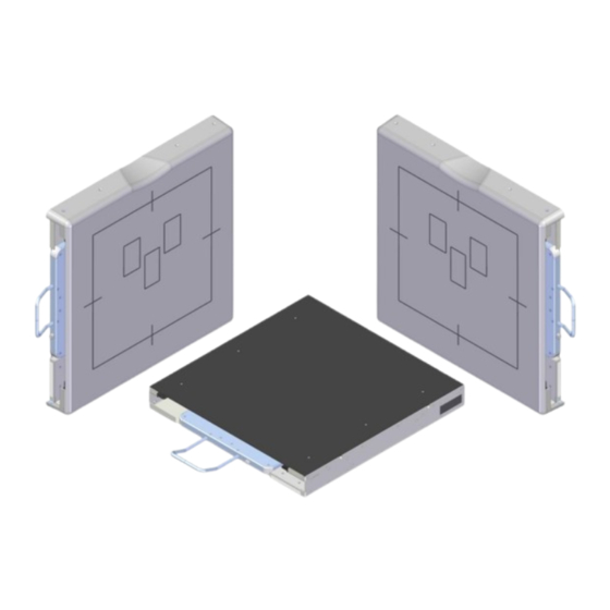
2.4. Overview of the device Harmony3 table model example Harmony3 wall model example 2.5. Restrictions on use RF communication devices should be kept at a minimum distance of 30 cm. Otherwise the performance of the device can be negatively influenced. 2.6. -
Page 11: Installation
Installation 2.11. The installation instructions for the device are available in the Technical Manual. For more information, contact your distributor or Varex Imaging Nederland B.V. User Manual: UM19893-EN Harmony3 series Revision: 5.0 www.vareximaging.com Date of release: 2019-01-29 11/20... -
Page 12: Operating Instructions
3. Operating instructions 3.1. Switching the device ON and OFF The Harmony3 series does not have a separate switch for switching the device on or off and is operational when the entire X-ray system is powered on. 3.2. Opening the drawer (optional feature) Pull out the drawer using the metal handle and by pushing the knob. -
Page 13: Removing The Detector
4. Level the detector and lock it behind the grip(s) in the front. WARNING: When inserting the detector, make sure the detector is detected correctly. If the detector is inserted correctly the Detector Present and correctly inserted LED lights up (Optional feature) Removing the detector 1. -
Page 14: Changing Detector Orientation (Optional Feature)
CAUTION: When not correctly inserted, exams might not be possible. Only place a removable grid if the “Varex Imaging upgrade-kit” is installed onto the grid. 1. Place the grid in the designated guide rails. 2. Push it in as far as possible. -
Page 15: Removing A Grid
3.5. Removing a grid NOTE In case the Harmony3 series is equipped with the “Internal Lock”-functionality, it is necessary to push and hold the knob next to the handle before the grid can be removed. Without grid lock option Pull the handle; the grid snaps loose and can be removed from the unit. The blue LED is switched off. -
Page 16: Disposal And Emc Compatibility
6. Disposal and EMC compatibility 6.1. Disposal This device contains substances that can be hazardous to the environment and care should be taken when disposed of. The device is marked with the following symbol: Follow national and local regulations regarding disposal of electronic equipment. Packaging material shall be recycled according national and local regulations. -
Page 17: Specifications And Accessories
7. Specifications and accessories 7.1. Technical specifications Description Reference Classifications See § 2.10 Application Holding an image receptor, part of an X-ray system Materials ABS, POM, stainless steel, aluminium Power source (ST and NR version 12-42 [VDC] ± 10% / 24 [VA] excluded) Detector/Grid present contact Contact closed when detector/grid is present. -
Page 18: Labels And Symbols On The Device
7.2. Labels and symbols on the device Product label Anholtseweg 44 7091 HB Dinxperlo The Netherlands Only www.vareximaging.com Medical Device Model: XXXXXXXXXXXXXXXXXX XXXXX-XX IPXX WOXXXXXX/E-XX YYYY-MM-DD (01)0XXXXXXXXXXXX(11)XXXXXX(21)WOXXXXXX/E-XX This product complies with the requirements of 21 CFR Subchapter J for radiation emitting products in effect on the date of manufacture. Manufacturer information Space for applicable (IEC) symbols Model name... -
Page 19: Box Label
Box label Only Anholtseweg 44 7091 HB Dinxperlo The Netherlands www.vareximaging.com Model: XXXXXXXXXXX Medical Device XXXXX-XX WOXXXXXX/E-XX YYYY-MM-DD (01)0XXXXXXXXXXXX (11)XXXXXX (21)WOXXXXXX/E-XX 7.3. Accessories The Harmony3 series is supplied without any accessories. The following accessory is available for the removable grid functionality: Amount Description Reference... -
Page 20: User Manual: Um19893-En Harmony3 Series Revision
+63 2 8076 472 Philippines.CNC@vareximaging.com © 2018 by Varex Imaging Nederland B.V. All Rights reserved. No part of this document may be reproduced or transmitted in any form or by any means, electronic, mechanical, photocopying, recording, or otherwise, without prior written permission of Varex Imaging Nederland B.V..
Need help?
Do you have a question about the Claymount Harmony3 Series and is the answer not in the manual?
Questions and answers