Table of Contents
Advertisement
Advertisement
Table of Contents

Related Manuals for Thermo Scientific Thermo Scientific Microm HM550 Series


Summary of Contents for Thermo Scientific Thermo Scientific Microm HM550 Series
- Page 1 Thermo Fisher Scientific Operation Manual HM550 Part of Thermo Fisher Scientific...
- Page 2 Operation Manual HM550 Thermo Fisher Scientific...
- Page 3 Microm HM550 Thermo Scientific CRYOSTAT MICROTOM incl. options O M V P D Operation manual – English ex Ser. No 46320 Thermo Fisher Scientific Operation Manual HM550...
- Page 4 © 2010 ermo Fisher Scientific. All rights reserved. ermo Fisher Scientific Microm International GmbH is an ISO 9001 Company. ermo Scientific is the trading name of ermo Fisher Scientific Microm International GmbH. All other trademarks are the property of ermo Fisher Scientific and its subsidiaries. ermo Fisher Scientific makes every attempt to ensure that the information contained in this support documentation is correct and clearly stated but does not accept responsibility for any errors or omissions.
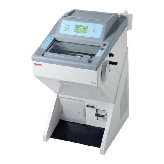
- Page 5 Figure 1. Cryostat Thermo Scientific Microm HM550. Thermo Fisher Scientific Operation Manual HM550...
- Page 6 Preface Certification ermo Fisher Scientific Microm International GmbH certifies that this instrument has been tested and checked carefully. Its technical data was verified before shipment to be in accordance with the published specifi- cations. e instrument complies with applicable international safety regula- tions.
- Page 7 Preface Intended use Dear valued Customer, ank you for buying this ermo Fisher Scientific instrument. Before putting the instrument into operation, please read these operat- ing instructions carefully to familiarize you with its proper operation and functions. e Cryostat series Microm HM550 are highly efficient cryostats for sectioning techniques in routine and research.
-
Page 8: Table Of Contents
Table of Contents Table of Contents Chapter 1 Safety Precautions Warning signals and symbols Introduction Chapter 2 Description of the HM550 Series Technical data HM550 Series Chapter 3 Operating instructions Setting up the cryostat Initial commissioning Basic operational rules Cutting process Cutting movement and retraction Setting section thickness and trimming thickness Chamber cooling... - Page 9 Table of Contents Specimen orientation Knife carriers Standard knife carrier Disposable blade carrier EC Disposable blade carrier EC 70 Magnetic disposable blade carrier MC Option O – specimen cooling Actual and set value of the specimen temperature Specimen orientation with zero device (with option O) Option M –...
- Page 10 Table of Contents Working with the cryostat Chapter 5 Preparations on the microtome and inside the cooling chamber Freezing-on the specimen Orientation and trimming of specimens Sectioning and taking off sections How to avoid malfunctions Possible sources of errors – cause and removal Chapter 6 Maintenance and care of the cryostat Shutting-off...
-
Page 11: Safety Precautions
Safety Precautions Warning singals and symbols Chapter 1 Safety precautions Warning signals e installation and routine use of the HM550 Series is easy and safe if and symbols the instructions in this manual are being observed. Note: Special instructions regarding operation of the instrument. WAꢀꢁIꢁꢂ... - Page 12 Safety Precautions Warning singals and symbols nstrument rounding Tꢉ ꢄꢎꢉꢃꢏ ꢃꢊꢖꢇꢆꢋ ꢒꢆꢉꢌ ꢁꢅꢁꢂꢈꢆꢃꢂꢄꢅ ꢂꢇꢆꢆꢁꢊꢈ, ꢈꢓꢁ ꢃꢊꢍꢈꢆꢇꢌꢁꢊꢈ ꢌꢇꢍꢈ ꢔꢁ ꢂꢉꢊꢊꢁꢂꢈꢁꢏ ꢕꢃꢈꢓ ꢈꢓꢁ ꢀꢆꢉꢈꢁꢂꢈꢃꢎꢁ ꢁꢄꢆꢈꢓ. Tꢓꢁ ꢃꢊꢍꢈꢆꢇꢌꢁꢊꢈ ꢃꢍ ꢁꢑꢇꢃꢀꢀꢁꢏ ꢕꢃꢈꢓ ꢄ ꢈꢓꢆꢁꢁ ꢕꢃꢆꢁ ꢐꢆꢉꢇꢊꢏ ꢀꢅꢇꢐ. Tꢓꢁ ꢀꢉꢕꢁꢆ ꢉꢇꢈꢅꢁꢈ ꢌꢇꢍꢈ ꢔꢁ ꢂꢉꢊꢊꢁꢂꢈꢁꢏ ꢈꢉ ꢈꢓꢁ ꢀꢆꢉꢈꢁꢂꢈꢃꢎꢁ ꢁꢄꢆꢈꢓ ꢄꢊꢏ ꢌꢇꢍꢈ ꢌꢁꢁꢈ ꢈꢓꢁ Iꢊꢈꢁꢆ- ꢊꢄꢈꢃꢉꢊꢄꢅ...
- Page 13 Safety Precautions Warning singals and symbols azard of malfunction Tꢉ ꢄꢎꢉꢃꢏ ꢈꢓꢁ ꢓꢄꢜꢄꢆꢏ ꢉꢒ ꢌꢄꢅꢒꢇꢊꢂꢈꢃꢉꢊ ꢉꢒ ꢄꢊ ꢃꢊꢍꢈꢆꢇꢌꢁꢊꢈ, ꢃꢈ ꢌꢇꢍꢈ ꢉꢊꢅꢋ ꢔꢁ ꢉꢀꢁꢆꢄꢈꢁꢏ ꢃꢊ ꢄ ꢂꢉꢊꢈꢆꢉꢅꢅꢁꢏ ꢁꢅꢁꢂꢈꢆꢉꢌꢄꢐꢊꢁꢈꢃꢂ ꢁꢊꢎꢃꢆꢉꢊꢌꢁꢊꢈ. Tꢓꢃꢍ ꢌꢁꢄꢊꢍ, ꢈꢓꢄꢈ ꢈꢆꢄꢊꢍꢌꢃꢈꢈꢁꢆꢍ ꢍꢇꢂꢓ ꢄꢍ ꢌꢉꢔꢃꢅꢁ ꢀꢓꢉꢊꢁꢍ ꢌꢇꢍꢈ ꢊꢉꢈ ꢔꢁ ꢉꢀꢁꢆꢄꢈꢁꢏ ꢃꢊ ꢈꢓꢁꢃꢆ ꢂꢅꢉꢍꢁ ꢎꢃꢂꢃꢊꢃꢈꢋ. Iꢊ...
-
Page 14: Introduction
Introduction Description of the HM550 Series Chapter 2 Introduction Description of the Open top cryostat. Modular design. Stainless steel cooling chamber. HM550 Series Chamber temperature regulation variable from -10°C down to -35°C. When the instrument is equipped with the option O, the specimen temperature can be controlled from +10°C down to -50°C. - Page 15 Introduction Description of the HM550 Series Basic outfit with three specimen chucks, 118 ml freezing medium, 100 ml cryostat oil, brush shelf and section waste tray, consisting of two parts. Option M Electric motor drive with electronic control of the cutting stroke. Cutting speed variable from 0 to 250 mm/s.
-
Page 16: Technical Data Hm550 Series
Introduction Technical data HM550 Series Technical Data HM550 Series Specimen temperature +10°C to -50°C control Chamber temperature -10°C to -35°C control Fast freezing station up to -35°C depending on the chamber temperature Actively cooled fast free- max. up to -60°C zing station with Peltier element Defrosting... - Page 17 Introduction Technical data HM550 Series HM550 Series Specimen orientation X- and Y-axes universal 8° with zero posi- tioning Z-axis up to 360° Coarse feed motorized, graduated, single and continuous Cooling chamber illumi- with variable illumination nation position Sliding window heated Option M Cutting drive manual and motorized, elect-...
- Page 18 Introduction Technical data HM550 Series HM550 Series Frequency Ultrasonic-unit 1.63 MHz + 70 kHz Transportation and storage conditions Storage temperature range -20°C to +50°C Operating conditions +5°C up to +35°C (at a max. rel. humidity of 60%) altitude up to 2000 m M.S.L. for indoor use only Floor loading requirements: 300 kg/m2...
- Page 19 Introduction Technical data HM550 Series OMVPD Information line Status line [11] [12] [10] Figure 2. Touchpad Keyboard with buttons and LC-display. [1]ꢀ Onꢀindicationꢀ(sleepꢀstatus)ꢀ ꢀꢀ [2]ꢀ Buttonꢀspecimenꢀtemperatureꢀꢀ ꢀ (Standardꢀversionꢀnotꢀused,ꢀasꢀthereꢀisꢀnoꢀspecimenꢀcooling) [3]ꢀ Buttonꢀchamberꢀtemperatureꢀ ꢀ [4]ꢀ ButtonꢀTRIM/FEEDꢀ ꢀ [5]ꢀ ArrowꢀbuttonꢀUPꢀ ꢀ [6]ꢀ ArrowꢀbuttonꢀDOWNꢀ ꢀ [7]ꢀ...
- Page 20 Introduction Technical data HM550 Series Figure 3. Keypad left. [1]ꢀ Buttonꢀcuttingꢀwindowꢀ ꢀꢀ [2]ꢀ ButtonꢀACAꢀ ꢀ [3]ꢀ Buttonꢀcoarseꢀfeed,ꢀforwardsꢀ ꢀ [4]ꢀ Buttonꢀcoarseꢀfeed,ꢀbackwardsꢀ ꢀ [5]ꢀ ButtonꢀTRIM Operation Manual HM550 Thermo Fisher Scientific...
- Page 21 Introduction Technical data HM550 Series Figure 4. Keypad right. [1]ꢀ Buttonꢀoperatingꢀmodesꢀ ꢀꢀ [2]ꢀ Operatingꢀknobꢀ ꢀ [3]ꢀ ButtonꢀSTART/STOPꢀ ꢀ [4]ꢀ ButtonꢀSTART/STOPꢀ ꢀ [5]ꢀ EmergencyꢀstopꢀLED [6]ꢀ Buttonꢀtoꢀactivateꢀtheꢀhandꢀwheelꢀbrake [7]ꢀ BrakeꢀLED [8]ꢀ Buttonꢀtoꢀloosenꢀtheꢀhandꢀwheelꢀbrake Thermo Fisher Scientific Operation Manual HM550...
- Page 22 Introduction Technical data HM550 Series Frontal View ꢀear View Operation Manual HM550 Thermo Fisher Scientific...
- Page 23 Introduction Technical data HM550 Series Lateral View Left Side Lateral View ꢀight Side Thermo Fisher Scientific Operation Manual HM550...
-
Page 24: Operating Instructions
Operating instructions Setting up the cryostat Chapter 3 Operating Instructions Setting up the cryostat Unpacking the instrument: • Cut through the three packing straps and remove the packing. • Remove the upper wooden cover (fig. 5.1). • e hinges of the upper wooden cover are secured with tape. •... - Page 25 Operating instructions Setting up the cryostat Figure 5a. Removing the bottom plate Figure 5b. Allan Key SW 6 for hight adjustment of the cryostat. Note: e upper wooden cover now serves as an incline (fig. 5a.1) on which the cryostat can be moved from the pallet to the floor by using the handle (fig. 5a.2) •...
- Page 26 Operating instructions Setting up the cryostat aution e instrument is very heavy. While the instrument rolls down on the incline, it must be guaranteed that the instrument does not move in an uncontrolled way. • Now the cryostat can be rolled to its site of installation. •...
- Page 27 Operating instructions Setting up the cryostat Note: Both measures reduce the formation of frost and therefore result in more favorable work conditions. A high air moisture as well as high ambient temperatures reduce the maximum performance of the instrument. • To fix the complete unit, tighten the screws (fig.
- Page 28 Operating instructions Setting up the cryostat • Loosen the transportation screw (fig. 6b.1) via the Allan key, size 6. • Now fix the separately packed handwheel handle on the handwheel with the attached screw by means of the Allan key. Afterwards: •...
-
Page 29: Initial Commissioning
Operating instructions Initial turn-on Note: e serial interface (fig 7.4) must only be used for service purposes and must not be used by the user for its intended use. Only ermo Scientific specific programming instruments must be connected to this interface. Initial commissioning Note: e kind of the used examination materials and all special conditions for... -
Page 30: Basic Operational Rules
Operating instructions Basic operational rules Note: Only for option M! If the foot pedal is not connected, there is the operating mode emergency stop (see page 84). is way, the hand wheel brake is activated and the cutting drive motor cannot be started. Always connect the foot pedal, if the instru- ment is equipped with option M! •... - Page 31 Operating instructions Basic operational rules OMVPD Figure 9. Display starting window. e instrument switches to the standby status (fig. 10) when it is turned on, but not operated for more than a pre-selected active time (see “ACTIVE Time”, page 51)) between 1 and 9 h. e chamber illumination goes off...
- Page 32 Operating instructions Basic operational rules • To return to the active operating state, press any key on the control panels or move the hand wheel. Also when reaching the WAKE time (see page 53) the instrument is in the active state again. ꢃP/DOWꢁ...
- Page 33 Operating instructions Basic operational rules Enter/scroll button Within the submenu, basic settings are carried out, further submenus are called and other functions are activated via this button (fig. 12.10). During operation of the instrument, e.g. while cutting, this button is used to choose between the indication of the section thickness, section sum, real time and indication of the distance to the end position of the specimen.
-
Page 34: Cutting Process
Operating instructions Cutting process Cutting process Cutting movement and • Turn the hand wheel in a clockwise direction so the cutting move- retraction ment is carried out. • As the specimen moves down, sections are produced. • Continue turning the hand wheel clockwise to bring the specimen back up. -
Page 35: Setting Section Thickness And Trimming Thickness
Operating instructions Setting section thickness and trimming thickness Setting section Basic status of the operating control: thickness and • To choose between section thickness and trimming thickness, press trimming thickness button (fig. 16.4). • e selected setting is shown inverted on the display (fig. 15). •... -
Page 36: Chamber Cooling
Operating instructions Chamber cooling e graduation of the trimming thicknesses (which can be pre-selected) is divided into 4 ranges: ꢀange ꢂraduation from 5 µm to 10 µm 5 µm from 10 µm to 100 µm 10 µm from 100 µm to 200 µm 20 µm 50 µm from 200 µm to 500 µm... -
Page 37: Function Fast Freezing For Standard Instruments
Operating instructions Chamber cooling returns to its basic indications after three seconds, i.e. fine section thickness is again shown inverted. Figure 18. Center keyboard, left buttons. Fastfreezing for standard ere are several possibilities to freeze on specimens. instruments Various specimen chucks are available. Round specimen chucks can be supplied with a diameter of 30 mm and 40 mm and rectangular specimen chucks with a size of 50, 55, 60 and 70 mm. -
Page 38: Heat Extractors (Optional Accessories)
Operating instructions Chamber cooling Note: e upper side of the freezing station must not be covered by frost or ice. To avoid this, use ethanol (absolute) or the like. Note: If the instrument is equipped with the option P (active deep freezing device with Peltier element), please also see page 100, Option P. - Page 39 Operating instructions Chamber cooling Figure 20a. Heat Extractor. Figure 20b. Heat Extractor. Thermo Fisher Scientific Operation Manual HM550...
-
Page 40: Feed
Operating instructions Feed Feed Specimen coarse feed For the fast forward and backward travel between knife and specimen, the cryostat microtome has a motorized coarse feed system. e approach between specimen and knife can also be carried out by means of an automatic function (see page 43). ꢀeturn travel of the •... -
Page 41: Speed Of The Specimen Coarse Feed
Operating instructions Feed When the instrument is just carrying out the retraction movement and the function coarse feed forwards is selected, the coarse feed movement is carried out and the retraction is annulled. • When the front end position of the specimen clamping is reached, the coarse feed turns off. -
Page 42: Setting The Cutting Window
Operating instructions Feed Note: One star means a slow approach speed, two stars mean a medium speed and three stars stand for a fast approach speed. • Press the enter button (fig. 23.10) to confirm the setting. Note: You return immediately to the list of submenus. If the setting is not con- firmed via the enter button, you will quit the submenu automatically after five seconds and you return into the list of submenus. -
Page 43: Automatic Approach System
Operating instructions Feed Manual setting • e cutting window can be determined by manual entries. • For this, press button (fig. 23.8) and while this button (fig. 23.8) is still being pressed, press button (fig. 25.1). • Turn the hand wheel so that the lower edge of the specimen is positi- oned slightly above the knife edge. - Page 44 Operating instructions Feed can only be applied after the specimen will have adjusted itself to the respective temperature of the specimen holder which must be between the temperature range. Starting the automatic approach • Use the hand wheel to make sure that the most protruding point of the specimen is opposite the knife edge.
- Page 45 Operating instructions Feed • e specimen clamping moves forwards until the knife edge touches the specimen. • Immediately afterwards, this forward travel of the specimen clam- ping is stopped and moved backwards by a safety distance of 200 µm. AUT.APPROACH is still shown on the display as the process of the automatic approach has not yet been finished.
-
Page 46: Trimming And First Cuts
Operating instructions Feed Note: In this case the function automatic approach cannot work. e approach between specimen and knife edge must be carried out via the coarse feed button (fig. 25.3). Trimming and first cuts After the specimen and the knife are adjusted, further gradual feed for trimming can be carried out using the function trimming. -
Page 47: Turning On/Off The Function Retraction
Operating instructions Turning on/off the function retraction • Turn the hand wheel in a clockwise direction to feed the specimen at the selected section thickness. Note: If the fine feed is carried out via the motorized drive (see Option M – Mo- torized Cutting Drive, page 80 and page 123). -
Page 48: Indication Of Cutting Processes
Operating instructions Indication of cutting processes Note: e letter “R”, however, might still be on. is function goes off only after having passed from the return travel again to the cutting movements via the hand wheel. Figure 28. Center keyboard, left buttons. [10] Figure 29. -
Page 49: Section Counter
Operating instructions Indication of cutting processes • Press the scroll button (fig. 30.10) until the required information lights up on the display. • If no information is required in this line of the display, press button (fig. 30.10) until this line is blank. [10] Figure 30. -
Page 50: Sum Of Section Thickness
Operating instructions Real time OMVPD Figure 32. Display: Section thickness sum. ꢀemaining travel to front • is value shows the distance in microns, which is left for sectio- ning. end position • When the specimen clamping is in the rear end position, the display shows 23 000 µm. -
Page 51: Setting The Real Time, Wake Time, Active Time And Date
Operating instructions Setting the real time, WAKE time, ACTIVE time and date OMVPD Figure 34. Display: Real time indication. Setting the real time, WAKE time, ACTIVE time and date Setting the real time • Press the menu button (fig. 38.9). is way, you get into the list of the submenus. - Page 52 Operating instructions Setting the real time, WAKE time, ACTIVE time and date Figure 36. Display: Real time adjusted. Figure 37. Center keyboard, left buttons. [10] Figure 38. Center keyboard, right buttons. Note: You return immediately to the list of submenus. If the setting is not con- firmed via the enter button, you will quit the submenu automatically after five seconds and you return into the list of submenus.
-
Page 53: Setting The Wake Time
Operating instructions Setting the real time, WAKE time, ACTIVE time and date Setting the WAKE time e WAKE time is used to trigger the instrument back into the active state. It should be set with sufficient time before work is started (approx. 1,5 h). -
Page 54: Setting The Active Time
Operating instructions Setting the real time, WAKE time, ACTIVE time and date Figure 40. Display: WAKE-Time adjusted. Figure 41. Center keyboard, left buttons. [10] Figure 42. Center keyboard, right buttons. Setting the ACTIVE time • Press the menu button (fig. 46.9). is way, you get into the list of the submenus. - Page 55 Operating instructions Setting the real time, WAKE time, ACTIVE time and date • To change the ACTIVE time at intervals of 1-hour-steps (1 to 9 h), press the arrow buttons (fig. 45.5 or 45.6). • Confirm it via the enter button (fig. 46.10). Note: You return immediately to the list of submenus.
-
Page 56: Setting The Date
Operating instructions Setting the real time, WAKE time, ACTIVE time and date Figure 45. Center keyboard, left buttons. [10] Figure 46. Center keyboard, right buttons. Setting the date • Press the menu button (fig. 50.9). is way, you get into the list of the submenus. - Page 57 Operating instructions Setting the real time, WAKE time, ACTIVE time and date Ver. 2.09 Figure 47. Display: Adjust Date. Figure 48. Display: Date adjusted. • To quit the submenu, press the menu button (fig. 50.9). • Now continue working with the selected settings. Figure 49.
-
Page 58: Defrosting
Operating instructions Defrosting [10] Figure 50. Center keyboard, right buttons. Defrosting Setting the defrosting • Press the menu button (fig. 54.9). is way, you get into the list of time submenus. • Via the arrow buttons (fig. 53.5 and 53.6) select “Defrost Time”. is submenu is now shown inverted. - Page 59 Operating instructions Defrosting Figure 52. Display: Defrosting time adjusted. • To quit the submenu, press the menu button (fig. 54.9). • Now continue working with the selected settings. Note: Defrosting can only be carried out at the set defrosting time, if the real time is set correctly (see page 51).
-
Page 60: Defrosting Cycle
Operating instructions Defrosting Defrosting cycle Every 24 hours the evaporator in the rear part of the microtome cham- ber is defrosted automatically. • It is advisable to set the time of the defrosting cycle not during rou- tine working time (see page 54). •... - Page 61 Operating instructions Defrosting Note: Before starting the immediate defrosting, it is absolutely necessary to remove the section waste as well as the tissue arning Remove the specimen from the chamber when defrosting is carried out. e temperature inside the chamber rises and thus the tissue specimen would be damaged.
-
Page 62: Interrupting A Defrosting Cycle
Operating instructions Defrosting Interrupting a If needed, the daily defrosting can be interrupted or cancelled. defrosting cycle • For this, press the menu button (fig. 60.9) is way, you get into the list of submenus. • Via the arrow buttons (fig. 59.5 and 59.6) select the submenu “re- quest defrost”. -
Page 63: Emptying The Defrosting Liquid
Operating instructions Defrosting • To quit the submenu, press the menu button (fig. 60.9). • Now continue working with the selected settings. • e interrupted defrosting is shown in the status line on the display (fig. 61) as INTR. Note: A cancelled or interrupted defrost cycle must be repeated later on, as other- wise the evaporator will cover completely with frost and cannot cool any- more (see immediate defrosting, page 60). -
Page 64: Customer-Specific Settings
Operating instructions Customer-specific settings Figure 62. Container for defrosting liquid. Customer-specific e information on the display can be shown in various contrasts and settings in four different languages. Setting the contrast • To set the contrast higher or lower, press the menu button (fig. 65.9). -
Page 65: Selecting The Language
Operating instructions Customer-specific settings • To set the contrast of the stripes higher, constantly press the button up (fig. 64.5). • When the desired contrast has been achieved, press the enter button (fig. 65.10) for confirmation. • To quit the submenu, press the menu button (fig. 65.9). •... - Page 66 Operating instructions Customer-specific settings • Via the arrow buttons (fig. 68.5 and 68.6) select the submenu “lan- guage”. is submenu is now shown inverted. • Via the enter button (fig. 69.10) confirm this submenu and simulta- neously open it. • Via the arrow buttons (fig.
-
Page 67: Illumination Of The Cooling Chamber
Operating instructions Illumination of the cooling chamber Figure 68. Center keyboard, left buttons. [10] Figure 69. Center keyboard, right buttons. Illumination of the To illuminate the cooling chamber, a fluorescent lamp is located in the cooling chamber handle of the sliding window. •... -
Page 68: Service Settings
Operating instructions Service settings Ver. 2.09 Figure 70. Display: Illumination of cooling chamber. Figure 71. Center keyboard, left buttons. [10] Figure 72. Center keyboard, right buttons. Service settings Note: Menu service settings are only relevant for service technicians. Operation Manual HM550 Thermo Fisher Scientific... -
Page 69: Specimen Orientation
Operating instructions Specimen orientation Ver. 2.09 Figure 73. Service settings. Specimen orientation In many cases, the orientation of the specimen in relation to the cutting edge would be advantageous. is can easily be done by means of the orienting specimen holder on the microtome. -
Page 70: Knife Carriers
Operating instructions Knife carriers Knife carriers Standard knife carrier e standard knife carrier of the cryostat is easy to use. e knife can be inserted either from the side or from the front. e standard knife holder takes up commercially available conventional knives with c- and d-profiles. - Page 71 Operating instructions Knife carriers • en tighten the clamping screws (fig. 75.2) to fix the knife in its position. If the cutting area of the knife is no longer usable, the knife can be moved • Open the clamping screws (fig. 75.2) and move the knife to the left or right side as required.
-
Page 72: Disposable Blade Carrier Ec
Operating instructions Knife carriers Note: Usable cuts are only achieved at a clearance angle of 10° or more! Disposable blade e disposable blade carrier EC takes up all commercially available carrier EC low profile blades with a dimension of 80 x 8 mm and a facet angle of approx. - Page 73 Operating instructions Knife carriers • Fix the clamping plate with clamping lever (fig. 76.1) again in the blade carrier in reverse order. • To insert the blade, now loosen the clamping lever (fig. 76.1). Note: Press the clamping plate on its lower area to open the slot behind the clamp- ing plate.
- Page 74 Operating instructions Knife carriers Note: Usable cuts are only achieved at a clearance angle of 10° or more! Disposable blade carrier e disposable blade carrier EC takes up all commercially available low EC 70 profile blades with a dimension of 80 x 8 mm and a facet angle of ap- prox.
- Page 75 Operating instructions Knife carriers • Fix the clamping plate with clamping lever (fig. 77.1) again in the blade carrier in reverse order. • To insert the blade, now loosen the clamping lever (fig. 77.1). Note: Press the clamping plate on its lower area to open the slot behind the clamp- ing plate.
-
Page 76: Magnetic Disposable Blade Carrier Mc
Operating instructions Knife carriers • Bring the clamping lever (fig. 77.3) into clamping position. • e selected clearance angle is now fixed in its position. Note: Usable cuts are only achieved at a clearance angle of 10° or more! Magnetic disposable e magnetic disposable blade carrier takes up ermo Scientific Microm blades with the dimensions 80 x 19 mm and/or 60x19 mm and a facet blade carrier MC... -
Page 77: Option O - Specimen Cooling
Operating instructions Option O – specimen cooling • Turn the lever (fig. 78.2) to move the anti-roll plate (fig. 78.4). If the cutting area of the blade is no longer usable, the blade can be moved: • Put the blade slider onto the blade and shift it. Note: e blade slider must always be put on in a way that the inscription can be read. - Page 78 Operating instructions Option O – specimen cooling • Press button (fig. 80.2) for specimen temperature. • “SPECIMEN” is then shown inverted. e set value settings are made via the • up button (fig. 80.5) • down button (fig. 80.6) Note: e valid range of the set value goes from +10°C down to -50°C.
-
Page 79: Specimen Orientation With Zero Device (With Option O)
Operating instructions Option O – specimen cooling Specimen orientation with In many cases, the orientation of the specimen in relation to the cutting zero advice edge would be advantageous. is can easily be done by means of the orienting specimen holder on (with Option O) the microtome. -
Page 80: Option M - Motorized Cutting Drive
Operating instructions Option M – motorized cutting drive Note: e specimen orientation includes a zero device for the specimen (chuck is always parallel in relation to the knife). Zero position can be felt noticeably. Option M – Sectioning can be carried out either manually by turning the hand Motorized cutting wheel or by means of a motorized cutting drive. -
Page 81: Selecting The Operating Modes
Operating instructions Option M – motorized cutting drive • Continue turning the hand wheel clockwise to place the upper edge of the specimen just below the knife edge. • Press button (fig. 83.1) to set the lower limit of the cutting window. •... - Page 82 Operating instructions Option M – motorized cutting drive • e selected operating mode is shown on the display as CONTIN, SINGLE and INTERV and the corresponding LED in button (fig. 85.1) lights up. OMVPD Figure 84. Display: Setting the operation mode. Continuous stroke •...
-
Page 83: Setting The Cutting Speed
Operating instructions Option M – motorized cutting drive Single stroke • Press button (fig. 85.1) until the operating mode single stroke SINGLE is shown on the display. • Press the two start buttons (fig. 85.3 and 85.4) or the foot pedal once to release a single cutting cycle. -
Page 84: Hand Wheel Brake
Operating instructions Option M – motorized cutting drive Figure 86. Keypad right. Hand wheel brake Unintended movements of the specimen holder can be avoided via the hand wheel brake. is reduces the danger of being injured while adjusting specimen clamp and knife carrierꢞ arning When the instrument is turned off, the hand wheel brake is not operative. - Page 85 Operating instructions Option M – motorized cutting drive Figure 87. Keypad right. aution In case danger arises from cutting drive, activate the emergency stopꢞ Hand emergency stop • e hand emergency stop (fig. 89.1) is located above the right arm rest.
- Page 86 Operating instructions Option M – motorized cutting drive Note: After having activated the hand emergency stop, STOP is shown inverted on the display (fig. 90). • After having eliminated the danger and to continue sectioning, pull out the red button (fig. 89.1). •...
-
Page 87: Option V - Vacutome
Operating instructions Option V – Vacutome OMVPD Figure 90. Emergency stop activated. Figure 91. Foot pedal with interlock plug. Option V – Vacutome Setting the vacuum for stretching sections and disposing of section waste Setting the vacuum • To select the suction power or the required vacuum between 0 – 10, turn the operating knob (fig. -
Page 88: Inserting And Replacing The Filter Unit
Operating instructions Option V – Vacutome window. Outside the cutting window, the selected vacuum is turned off by means of a valve. Setting the suction window is carried out in the same way as the cutting window. Figure 92. Operating knob for adjusting suction power. Inserting and replacing When the suction power and suction window are set in a correct way, the section to be disposed of gets via the suction slot in the knife carri-... - Page 89 Operating instructions Option V – Vacutome Figure 93. Inserting and replacing the filter unit. • For this, remove the coarse filter as described above. • Use lab gloves!!! • Remove the coarse filter from the metal carrier by using forceps or the like.
- Page 90 Operating instructions Option V – Vacutome e internal counter for the coarse filter must be reset: • For this, press the menu button (fig. 95.9). is way, you get into the list of submenus. • Via the arrow buttons (fig. 94.8 and 94.6) select “coarse filter”. is submenu is now shown inverted.
- Page 91 Operating instructions Option V – Vacutome • To quit the submenu, press the menu button (fig. 95.9). • Now continue working with the selected settings. Note: If there is no time to reset the internal counter for the coarse filter, it is pos- sible to ignore the message “CHANGE COARSE FILT.”...
- Page 92 Operating instructions Option V – Vacutome Figure 96. Inserting and replacing the filter unit. e internal counter for the micro filter must now be reset: • For this, press the menu button (fig. 98.9). is way, you get into the list of submenus. •...
- Page 93 Operating instructions Option V – Vacutome Figure 97. Center keyboard, left buttons. [10] Figure 98. Center keyboard, right buttons. submenu is also chosen and will still be valid. • To quit the submenu, press the menu button (fig. 98.9). • Now continue working with the selected settings.
-
Page 94: Setting The Suction Window
Operating instructions Option V – Vacutome Setting the suction e size of this zone is shown in millimeters within the symbol for window the suction window. When passing the suction window this symbol is shown inverted on the display. Note: Cutting and suction window are identical. -
Page 95: Knife Carrier For Vacutome
Operating instructions Knife carrier for Vacutome Figure 100. Keypad left. Knife carrier for Vacutome Disposable blade e disposable blade holder EV takes up all commercially available low carrier EV profile blades with a dimension of 80 x 8 mm as well as high profile blades with a dimension of 76 x 14 mm an a facet angle of approx. - Page 96 Operating instructions Knife carrier for Vacutome Figure 102. Insert a blade into the disposable blade carrier EV. Inserting the blade • Insert the blade into the slot behind the clamping plate (fig. 101.1). Note: When using high profile blades, first loosen the lever (fig. 101.2) and remove the spacer strip.
- Page 97 Operating instructions Knife carrier for Vacutome • Loosen the clamping lever (fig. 101.2). e blade is no longer clamped and can be moved e.g. by means of a brush until a suitable position of the blade is found. • Clamp again the clamping lever (fig. 101.2) aution To avoid the danger of injury on the blade during adjustment of speci- men, always position the knife guards (fig.
-
Page 98: Magnetic Disposable Blade Carrier Mv
Operating instructions Knife carrier for Vacutome • Lift the vacuum anti-roll hood (fig. 102.4), the flap (fig. 102.6) beneath falls back in place and the slot gets closed. Magnetic blade e magnetic blade carrier is suitable to take up ermo Scientific carrier MV Microm blades with the dimensions 60 x 19 mm and a facet angle of approx. - Page 99 Operating instructions Knife carrier for Vacutome Figure 104. Insert a blade into the magnetic blade carrier MV. Note: e blade slider must always be put on in a way that the inscription can be read. • is way, it is guaranteed that the slanted edge (fig. 104.5) of the blade slider shows to the rear side of the blade.
-
Page 100: Option P - Active Deep Freezing Device With Peltier Element
Operating instructions Option P – active deep freezing device with Peltier element Note: Usable cuts are only achieved at clearance angles between 24 – 30°! Moving the magnetic blade • To move the magnetic blade carrier, loosen the lever on the right carrier side of the base plate. - Page 101 Operating instructions Option P – active deep freezing device with Peltier element • Via the arrow buttons (fig. 107.5 and 107.6) select HEAT., COOL. or OFF. • Confirm the selected function via the enter button (fig. 108.10). • e Peltier functions are turned off automatically after 8 min. •...
- Page 102 Operating instructions Option P – active deep freezing device with Peltier element [10] Figure 108. Center keyboard, right buttons. • If “HEAT.” is selected, the Peltier element heats up until it has reached a positive end temperature. is way, tissue specimens can be detached from the chuck inside the chamber (fig.
-
Page 103: Cold D (Option Dc) Function
Operating instructions Cold D (Option DC) • Afterwards, the chuck together with the specimen is inserted with the peg into one of the four front fast freezing stations (fig. 111). ese four front fast freezing stations are equipped with a Peltier cooling element. - Page 104 Operating instructions Cold D (Option DC) e efficacy of microbial (and viral) inactivation was determined in analogy to the standard methods of the DGHM (German Society for Hygiene and Microbiology) and the European standard EN13697:2002-01 for quantitative non-porous surface testing for evaluation of chemical disinfectants with adaptations to the test item.
-
Page 105: Preparing To Perform Cold D
Operating instructions Cold D (Option DC) Preparing to perform To perform Cold D, the disinfectant tank (Fig. 112a.1) needs to be attached to the back of the unit with two screws (Fig 112a). is only Cold D needs to be done once. •... - Page 106 Operating instructions Cold D (Option DC) Figure 112a. Fast coupling of the Sanosil container. ® Note: To ensure that the Cold D system can function properly, always adhere to the sequence of operations specified above. arning To avoid the frosting of the chamber, the Cold D should not be used more than 2 times per day, plus 1 cycle overnight.
-
Page 107: Starting Cold D
Operating instructions Cold D (Option DC) Starting Cold D Note: e heated window must always be closed before starting Cold D. If the heated window has not been closed, the command “Please close the heated window” is displayed. • Press the Menu button (Fig. 113.9) to access the submenus listed. •... -
Page 108: Interrupting Cold D
Operating instructions Cold D (Option DC) Ver. 2.09 Figure 115. Starting the Cold D (Option DC). Interrupting Cold D e cycle can be aborted at any time by • Pressing the Reset button (Fig. 113.8). Note: At the end of the Cold D cycle, remove all debris from the chamber. If any ice has formed on the cryobar, it is easily removed by spraying with alcohol. - Page 109 Operating instructions Cold D (Option DC) Note: Selecting “On” restores the last mode selected in the “Option DC Mode” submenu. Ver. 2.09 Figure 116. Display: Cold D (Option DC) ON/OFF. “OPT. DC MODE” submenu is menu sets how often the Cold D will take place automatically. •...
- Page 110 Operating instructions Cold D (Option DC) Figure 118. Display: Cold D (Option DC) daily cycle. Figure 119. Display: Cold D (Option DC) weekly cycle. “OPT. DC TIME” submenu is menu sets the time of an automatic Cold D. • Press Enter (Fig. 113.10) to open the submenu. •...
- Page 111 Operating instructions Cold D (Option DC) Ver. 2.09 Figure 120. Display: Option DC, Real time. Figure 121. Display: Cold D (Option DC) real time set up. “WEEKDLY” submenu is option sets the day of the week that the automatic Cold D will take place (OPT.
- Page 112 Operating instructions Cold D (Option DC) • If the “Daily” cycle has been selected in the “OPT. DC MODE” submenu, you can select whether you wish Cold D to be performed at the weekend in this submenu. • Use the arrow keys (Fig. 114.5 and 114.6) to select either “Yes” or “No”...
-
Page 113: Orough Cleaning Of The Cooling Chamber
Operating instructions Cold D (Option DC) Figure 125. Display: Weekend turned off for weekly Cold D. “Disinfectant expiry date” is submenu is where the expiry date of the disinfection solution is submenu entered. A warning will appear on this date. •... -
Page 114: Error Code Indication
Operating instructions Error code indication Error code indication e instrument has an error code indication to define faster and better possible malfunctions. e error codes describe so-called system errors. Additionally, error mes- sages are shown on the display as text messages, e.g. when the temperature sensors are faulty, when the end position of the specimen clamping has not been reached, when there is a high pressure in the cooling system and when the function of the automatic approach system is faulty (see page 43). -
Page 115: Error Codes Of The Cold D (Option Dc) Function
Operating instructions Error code indication Error code `ꢁO EꢁD POSITIOꢁ´ Before turning on the instrument on the main switch, it carries out an automatic travel calibration of the specimen clamping. e specimen clamping is brought into that position which has the longest distance to the knife carrier. - Page 116 Operating instructions Error code indication 5. `CAꢃTIOꢁ: Option DC cycle If the Cold D cycle was interrupted by a power failure or by switching interrupted power failure or unit off the unit, this is indicated by this error code. Important: e Cold D switched off from power! Conti- cycle was not completed and should be restarted.
-
Page 117: Accessories
Operating instructions Accessories Accessoires e microtome cryostat HM550 series is equipped with the following accessories: Standard equipment Description Cat. ꢁo. 2 specimen chucks, 30 mm round 715710 1 specimen chuck, 40 mm round 715720 1 Allan key 2,5 mm 362220 1 Allan key 5 mm 362260 1 Allan key 6 mm... -
Page 118: Additional Equipment
Operating instructions Accessories Additional equipment Description Cat.-ꢁo. (optional) Specimen chucks ø 20 mm 715700 ø 30 mm 715710 ø 40 mm 715720 50 x 50 mm 715730 55 x 55 mm 715740 60 x 55 mm 715750 70 x 55 mm 715760 Cryo-Molds 10 mm... -
Page 119: Theory Of Operation
Theory of operation Specimen and chamber cooling, defrosting Chapter 4 Theory of operation Specimen and e chamber, the microtome and the specimen head are cooled by a chamber cooling, refrigeration machine. defrosting In the rear area of the microtome chamber is an evaporator which the cold coolant flows through as well as through the specimen head. - Page 120 Theory of operation Specimen and chamber cooling, defrosting Inevitably, when working on the microtome the dry cold air of the mi- crotome chamber mixes with the warm humid air outside the chamber. Frost forms on the finned evaporator. e increasing thickness of the frost reduces the efficiency of the evaporator.
-
Page 121: Cutting Movement
Theory of operation Cutting movement e microtome of this cryostat is a rustproof rotary microtome. Cutting movement e cutting movement is carried out by turning the hand wheel. e rotary movement results in the vertical and horizontal movement of the specimen clamp. Sectioning is carried out by knives or blades, which must be adjusted and fixed on the knife carrier. -
Page 122: Specimen Coarse Feed And Trimming Function
Theory of operation Specimen coarse feed and trimming stages Specimen coarse After changing the specimen or moving the knife or knife carrier, it is necessary to adjust the knife edge to the specimen again. is can easily feed and trimming be done by means of the coarse feed and the trimming function. -
Page 123: Option M - Motorized Cutting Drive
Theory of operation Option M – motorized cutting drive Option M – e motorized cutting drive facilitates routine work and ensures an even Motorized cutting cutting speed also for harder specimens. drive When using the motorized cutting drive a regulated D.C. motor works on the hand wheel of the cryostat microtome by means of an electrome- chanical clutch and a reduction gear. -
Page 124: Option O - Specimen Fast And Temperature Control
Theory of operation Option O – Specimen fast and temperature control e vacuum for stretching sections is turned off immediately after reaching the end of the specimen via an in-line valve, however, depend- ing on a correct setting of the cutting/suction window. Turn the vacuum anti-roll hood backwards to transfer the cut onto a slide. -
Page 125: Cold D (Option Dc)
Working with the cryostat Preparations on the microtome and inside the cooling chamber Cold D (Option DC) e Cold D (Option DC) is a fumigation unit for the application of disinfection media (Sanosil®) onto the operation areas in the cryo cham- ber which are accessible for the user during the intended use. -
Page 126: Freezing-On The Specimen
Working with the cryostat Freezing on the specimen Freezing-on the e specimen is frozen-on to the specimen chuck with clinging groves specimen by means of a freezing medium. To freeze-on specimens, use the fast freezing device or the active deep freezing device on the left side of the chamber. -
Page 127: Sectioning And Taking Off Sections
Working with the cryostat Sectioning and taking off sections With the motorized coarse feed specimen and knife can roughly be adjusted. e process of the first approach between specimen and knife edge can also be carried out via the automatic approach system. en carry out a further gradual feed by using the function trimming. -
Page 128: How To Avoid Malfunctions
Working with the cryostat How to avoid malfunctions How to avoid To cut usable sections, the following points are of utmost importance: malfunctions • Condition of the knife edge, probably move it horizontally to the left or right side. • Check adjustment of anti-roll guide and correct it, if necessary. - Page 129 Working with the cryostat How to avoid malfunctions Recommendation: Before touching the cylinder head or tempera- ture sensor, touch another metallic part, e.g. knife carrier, inner wall of chamber or waste tray to guarantee a safe discharge. • When working with the active deep freezing device, sufficient time must have been passed to allow this device reaching a temperature of -60°C.
-
Page 130: Possible Sources Of Errors - Cause And Removal
Working with the cryostat Possible sources of errors – cause and removal Possible sources of errors – cause and removal Problem Cause ꢀemoval Cryostat temperature cannot be Ambient temperature too high Lower ambient temperature by fresh air, achieved climate. Please note the specified temperature of +22°C! Cryostat is influenced by near, heat-generating Change site of installation... - Page 131 Working with the cryostat Possible sources of errors – cause and removal Problem Cause ꢀemoval Spacious specimen Trim the specimen in a parallel way; select a thicker section thickness Anti-roll plate not adjusted properly Readjust the anti-roll plate Anti-roll plate not aligned parallel towards the Align parallel knife edge Incorrect clearance angle...
-
Page 132: Maintenance And Care Of The Cryostat
Maintenance and care of the cryostat Shutting-off for cleaning Chapter 6 Maintenance and care of the cryostat Shutting-off for Cleaning, care and decontamination of the cryostat depends on how frequently the instrument is used. However, it is recommended to shut cleaning the instrument off... -
Page 133: Removing The Microtome
Maintenance and care of the cryostat Removing the microtome • Remove the sheets on the black grips with a circular movement upwards/forwards. Figure 127. Removing the side sheets. ꢀemoving the • In the left rear part of the microtome there is the so-called connec- microtome tor housing including the two electrical connections and for the option O (specimen cooling) two cool-technical quick couplings as... - Page 134 Maintenance and care of the cryostat Removing the microtome • For the option O pull off the quick coupling. For this, touch the connectors on the ring sleeve and pull them towards the operator to the front and pull the connector off. •...
- Page 135 Maintenance and care of the cryostat Removing the microtome [12] Read user manual before disconnecting [11] [10] Figure 129. Removing the microtome. • Move the microtome forwards and remove it from the cryo-chamber. • oroughly clean and wash the interior. aution Chloric cleaning agents must not be used for cleaning purposes.
-
Page 136: Cleaning And Care Of The Microtome
Maintenance and care of the cryostat Cleaning and care of the microtome Note: Please observe the filling level!! • e red stopper must be inserted after cleaning as otherwise cold air leaks out during cooling operation. us generating frost built-up. •... -
Page 137: Cleaning The Cooling Lamella
Maintenance and care of the cryostat Cleaning the cooling lamella • Put one or two drops into the space (fig. 132.2) of the cross roller bearings. • e specimen clamping should be in the lower position. • Also slightly lubricate the horizontal cylinder guide behind the specimen clamping. - Page 138 Maintenance and care of the cryostat Cleaning and care of the microtome Note: e grid of the cleaning hole is kept on the right side by a magnet (fig. 133.2) an is inserted on the left side. • Remove the dust from the cooling lamella by means of a commer- cially available vacuum cleaner.
-
Page 139: Changing The Fluorescent Lamp
Maintenance and care of the cryostat Changing the fluorescent lamp Changing the e fluorescent lamp L8/12 of the cryostat is integrated in the grip (fig. fluorescent lamp 135.1) of the heated sliding window. • Before exchanging the lamp, turn off the mains switch and unplug the instrument. -
Page 140: Conditions For The Transportation Of The Instrument
Conditions for the transportation of the instrument Taking back the instrument for repair or routine maintenance • Turn the starter (fig. 135.5) in a counter-clockwise direction and remove it from the socket. • Insert the new starter into the socket. •... - Page 141 Conditions for the transportation of the instrument Taking back the instrument for repair or routine maintenance • Before the transportation, empty all containers for defrosting liquid and disinfection solution to avoid the unintended release of the fluids. When removing the containers, please also note the precau- tionary measures which are described in the chapter “Safety Precau- tions”.
- Page 142 Conditions for the transportation of the instrument Taking back the instrument for repair or routine maintenance • To remove the container for the disinfection medium, first loosen the rapid action hose (fig. 136). en remove the container from the supports. •...
-
Page 143: Disposal Of The Instrument After Final Shutdown
Conditions for the transportation of the instrument Disposal of the instrument after final shutdown • Clean and disinfect the cryo chamber according to the respective applicable lab regulations. • Unscrew the hand wheel handle for transportation. Note: To make sure that these is no condensation water inside the chamber, let the instrument approx. -
Page 144: Appendix A Cryostat Disinfection
Appendix A Appendix A Cryostat disinfection Disinfection of the cryostat chamber as per protection level 2 as per the Regulation of Biological Substances Act (BioStoffV; GBGI. I S. 50; 1999 S. 2059) and the Technical Regulations on Biological Substances (TRBA 10; 09/1999). ꢀecommended Disin- Universal Precautions fection Procedure... -
Page 145: Certificate
Apendix B tion media, ermo Fisher Scientifi c Microm International GmbH as- sumes no liability concerning functionality and disinfection eff ectiveness. Appendix B Certfi cate Labor für Mikrobiologie und Ökotoxikologie Priv. Doz. Dr. Ingo Maier Hochgratweg 12 D-88779 Amtzell, Germany Microm International GmbH Tel +49 (0)7520 953 660 Mr Benjamin Hoffmann... - Page 146 Cryostat disinfection Cold disinfection in the cryostat Microm HM550 page 2 of 3 2. Experimental A detailed description of the experimental conditions is given in a separate test report [4]. 2.1 Test instrument Microm HM550 VPD cryostat, serial number 30883 2.2 Test strains The following test strains were used in the present study: Staphylococcus aureus ATCC 6538...
- Page 147 Cryostat disinfection, Option DC + Sanosil ® Cold disinfection in the cryostat Microm HM550 page 3 of 3 Reduction factors were determined in comparison to control experiments without treatment with disinfectant. Control experiments on the efficacy of neutralization and the toxicity of the neutralizing solution were also carried out.
- Page 148 Anatomical Pathology Otto-Hahn-Strasse 1 A 69190 Walldorf GERMANY + 49 (0) 6227-8360 4481 Campus Drive Kalamazoo, MI 49008 + 1 (800) 522-7270 www.thermofisher.com Operation Manual HM550 Thermo Fisher Scientific...
Need help?
Do you have a question about the Thermo Scientific Microm HM550 Series and is the answer not in the manual?
Questions and answers